A simple 2-element quad for 2m
last updated 26 March 2023.
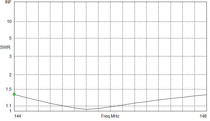
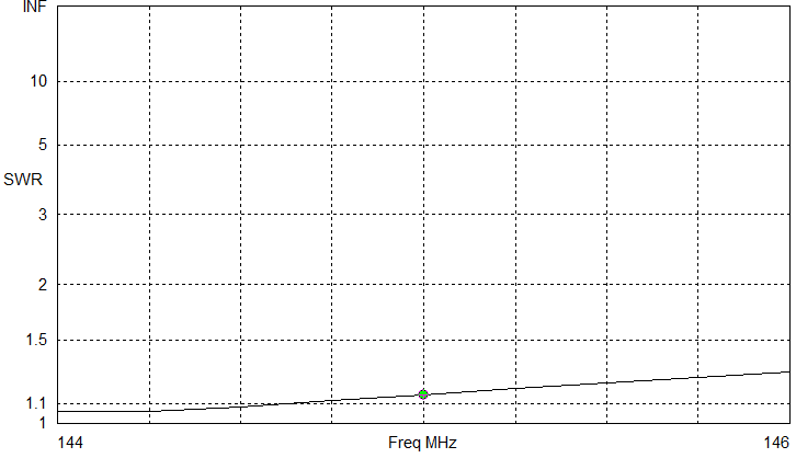
Here is a simple 2-element quad for 2m that is easy to build and does a good job. It works well for extending the range of an HT, transmitter hunting, SSB, or general use. When not in use it comes apart for storage. The SWR is less than 1.5 : 1 across the band from 144 to 148 MHz without any tuning. The boom can be rotated for either horizontal or vertical polarization.
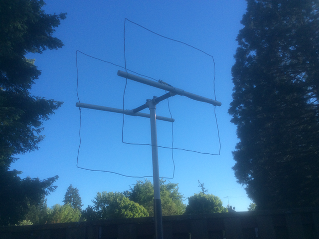
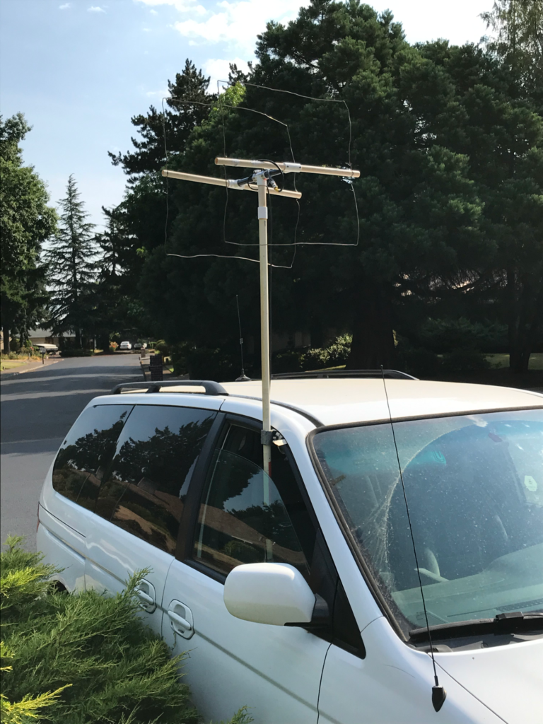
This is my favorite antenna for mobile transmitter hunts, as it doesn’t stick up as high above the roof as a yagi (for vertical polarization). A 3-element version has better performance, but is harder to turn at speed due to to the added wind drag. The wire elements occasionally catch on tree branches, but usually can be bent back into shape without any permanent damage.
The construction method shown here uses plastic PVC water pipe to support loops of 2 to 3 mm (AWG #14 to AWG #8) solid wire for the elements. You may need to adapt the design to use your locally available materials, but it shouldn’t be difficult.
For those who don’t need detailed instructions, the critical dimensions are: driven element 2085 mm ( 82 inches ) in circumference, reflector 2235 mm ( 88 inches ), spacing 330 mm ( 13 inches ), and fed through 1/4 or 3/4 wavelengths of 75 ohm coax.
If you only need it to cover 144 – 146 MHz, you can lengthen the elements slightly to 2100 mm and 2260 mm.
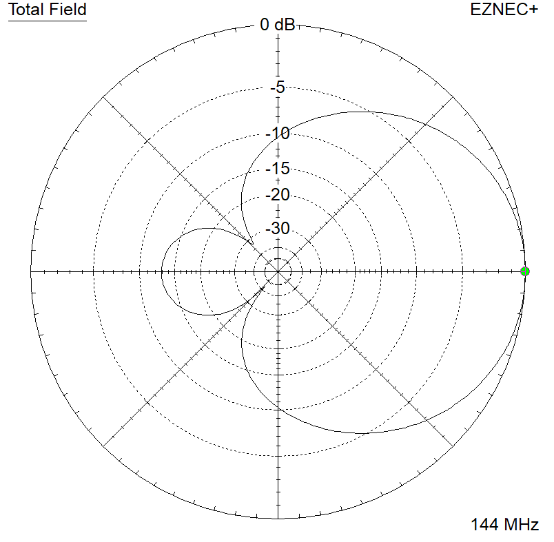
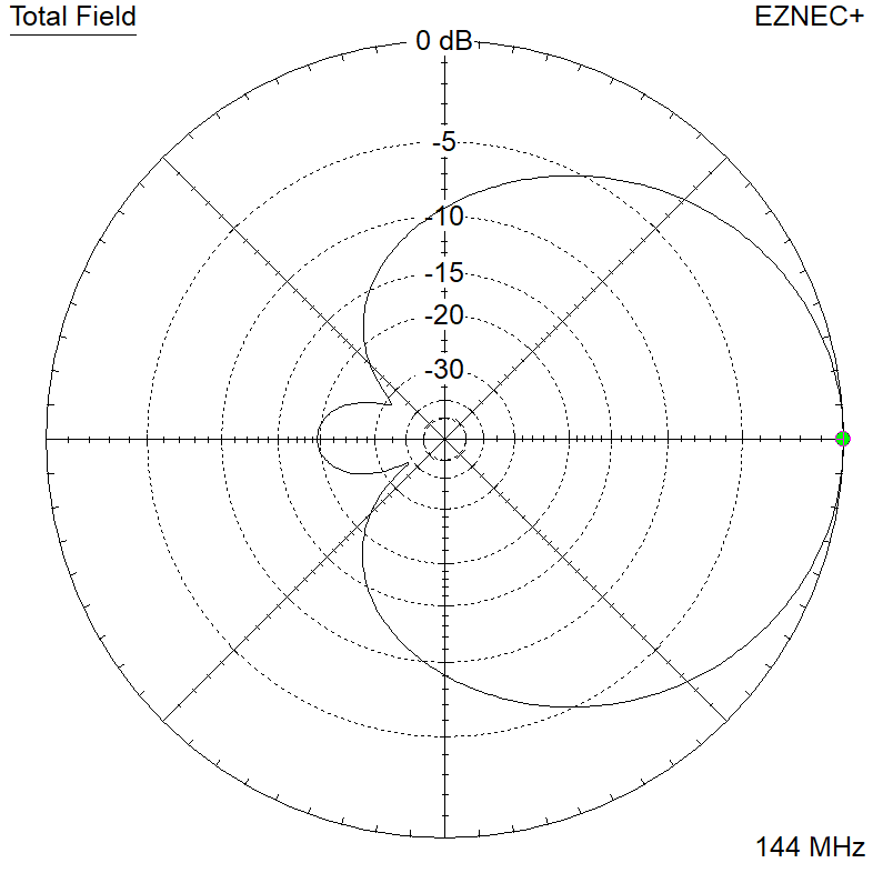
With either design, gain is highest at the bottom of the band, and F/B is best at the top of the band.
construction
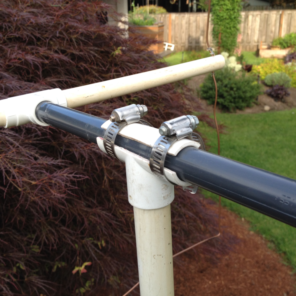
These particular dimensions make use of a common (in the USA) 305 mm ( 12 inch ) piece of plastic pipe with threaded ends (a “riser”) as the boom. This is the grey pipe you see in the photos. The elements are built onto T connectors with a matching thread, which allows them to be unscrewed to remove the elements.
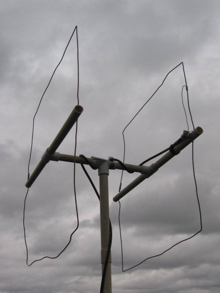
The frame is built is built using US nominal “1/2 inch” PVC pipe, which is actually 21.4 mm outside diameter. The mast and mating connector are US nominal “3/4 inch” PVC pipe, about 26 mm outside diameter. The mast-to-boom connector is made by cutting off a T fitting of the larger size and laying the small pipe inside it. The use of two different sizes of pipe permits a rotating joint (secured by hose clamps) so the antenna polarization can be changed, as shown in this photo:
Construction should be fairly obvious from the photos. Thinner wall (white) pipe is used for the spreaders, which are at least 1/8 of the element circumference. Drill holes in the spreaders for the wire – these are spaced 1/8 of the circumference from the center of the boom. You can cut all the spreaders long enough for the reflector to start with, then trim them later if you want.
If your wire has insulation on it, remove it. The easy way to do this is to use a knife to slice off one side of the insulation, down to the copper, with the wire under tension. Then the rest of the insulation pulls right off. I secure one end of the wire and walk backwards, with my thumb pressing the wire against the knife blade. It goes very quickly.
Add about 2 – 3 cm ( 1 inch ) extra to the reflector wire length for overlap for the splice. It doesn’t really matter where the splice ends up around the element. I find it easiest to measure 1/4 of the circumference near the center of the wire and make a right angle bend at each end, giving a “U” shape. Feed the ends of the wires through the holes in the spreaders, then measure up 1/4 of the circumference on each side, and bend the ends over to close the loop. Wrap some thin wire around the splice to hold it while you solder it.
The driven element is a bit different. Start with the wire at least 20 cm ( 8 inches ) longer than the final circumference, to allow for connections at the feedpoint. (The actual length required depends on the pipe size.) Prepare one of the spreaders in the normal way, with a hole 1/8 of the circumference out from the center.
On the other side of the spreader, drill two holes, one either side of the expected distance, spaced 1 cm ( 1/2 inch ) or so apart. Find the center of the wire and center it in the spreader with the single hole. Measure and bend the sides around from there, then pass each of the ends through one of the two holes in the other side of the spreader. Don’t solder them together – these will become the feedpoint.
For each of the wires, check the measurement from the last bend to the center of the spreader, then bend the excess wire around the spreader and around the wire where it enters the spreader. That secures the wire so it doesn’t slide. Make both bends around the SAME side of the spreader.
Matching the antenna requires 1/4 or 3/4 wavelength of 75 ohm coax cable. There are two basic types in the USA: RG-59 usually has a solid polyethylene dielectric with a velocity factor of 0.67, requiring a length of 355 mm ( 14 inches ) or 1067 mm ( 42 inches ). RG-6 has a foam dielectric with a velocity factor of 0.82, needing 432 mm ( 17 inches ) or 1270 mm ( 50 inches ). These lengths include an 25 mm ( 1 inch ) of cable for the connections. If you don’t know the velocity factor of your 75 ohm coax, use 405 mm ( 16 inches ), or cut it on the long side and trim the length for lowest SWR.
One end of the 75 ohm coax connects to the feedpoint of the antenna, the other has a connector to join to your 50 ohm feedline to the radio. If all you have is 75 ohm coax, connect it to the antenna and adjust the full length for minimum SWR at your desired frequency.
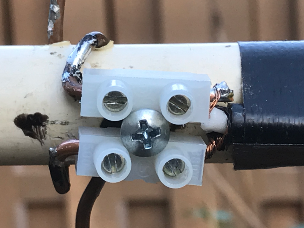
To connect the coax to the antenna, strip back the braid and slip it under the loop of wire passing through the hole closest to the boom. Pass the center conductor under the loop of wire furthest from the boom, and solder both. Weather proof the connection with some sort of sealant.
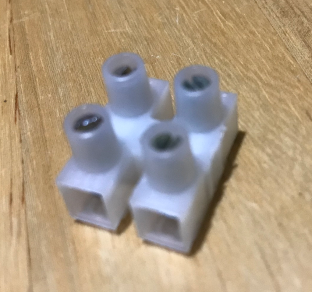
The next time I build a quad I will try using a terminal block like that in the photo to secure the wires and connect the feedline without needing to solder. That will make it easier.
If the wires slip through the holes in the spreaders, you can bend the wires on either side of the hole, add a drop of glue or solder, or solder thin wires around the spreader to hold the wires in place.
When the spreaders are horizontal, the feedpoint is on one vertical side, so the antenna is vertically polarized (as shown in all the photos). For horizontal polarization, rotate the boom so the spreaders are vertical.
results
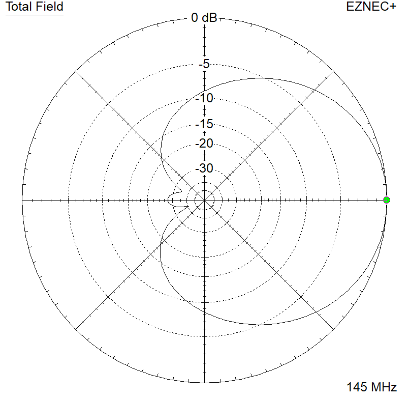
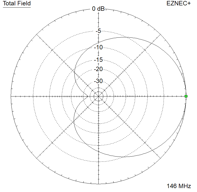
The modeled response of the original design is shown below:
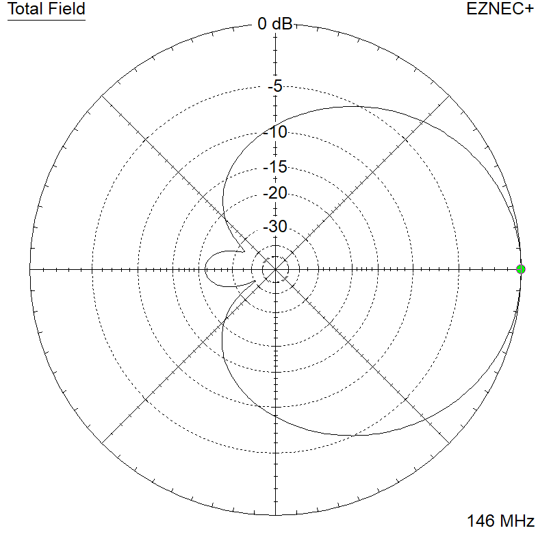
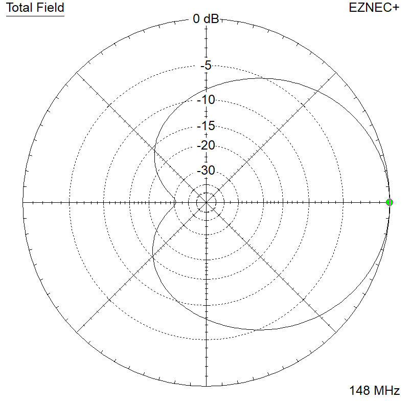
The 144 – 146 MHz dimensions give the following modeled results:
Of course, this construction method can be used for many other quad designs, adapted to the needs of the builder. I have used it around 120 MHz, but below that frequency the wire elements might need additional bracing. I’ve also used 3 mm (AWG #8) aluminum wire, with the elements joined by screw clamps rather than soldering. The internal metal parts of the terminal blocks shown above might work well for this, with some anti-oxidant paste in them to reduce contact corrosion.