End-Fed wires for NVIS
last updated 11 January 2022
An end-fed wire fed against ground is a simple and popular antenna. However, designing such an antenna to be an effective NVIS antenna, particularly across multiple bands, is not always an easy task.
For NVIS we want maximum radiation straight up, and a vertical wire won’t provide the desired pattern. We need the bulk of the radiation from the antenna to be horizontally polarized. Two common methods are a sloping wire, or an “inverted L antenna”:
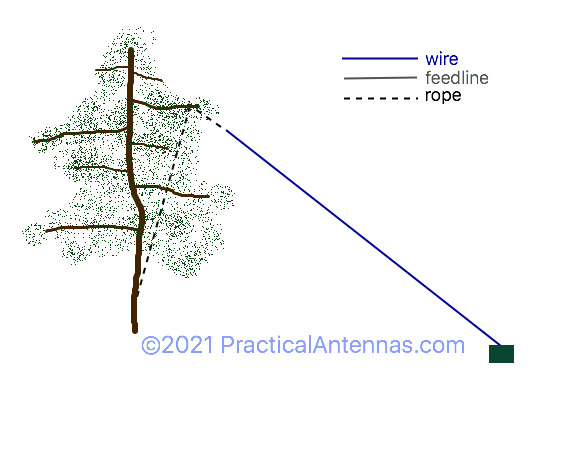
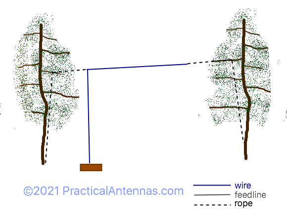
For optimum NVIS performance, the majority of the radiation needs to be horizontally polarized. For a sloper, that would suggest that the angle be 30 degrees from the ground, or less, which means that the height at the end of the wire is less than half the wire length. For the Inverted L, the vertical wire should be relatively short compared to the horizontal one: ideally, the horizontal wire would be longer than 1/4 wavelength so it includes a point of maximum current, but at low heights this isn’t as much of an issue. (Another option is to run the wire horizontally out the window of a building: this works well with metal window frames as a ground (if all the window frames are bonded together).
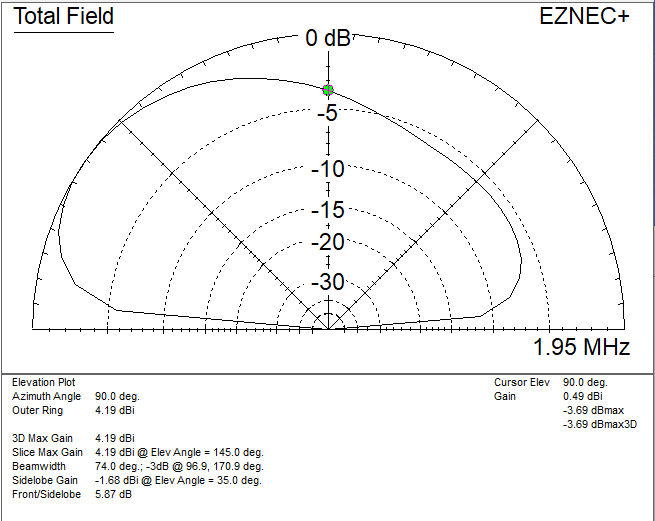
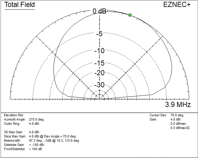
The patterns given here are nominal – they will vary with the exact dimensions and height above ground, and at different azimuth angles from the antenna.
sample patterns for a sloper
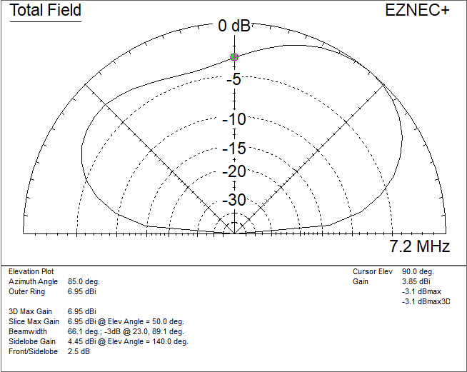
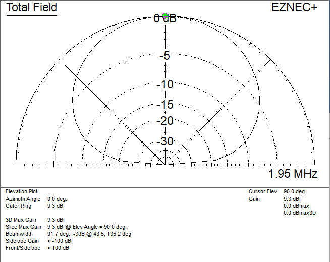
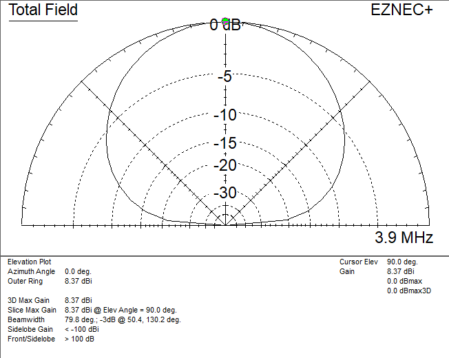
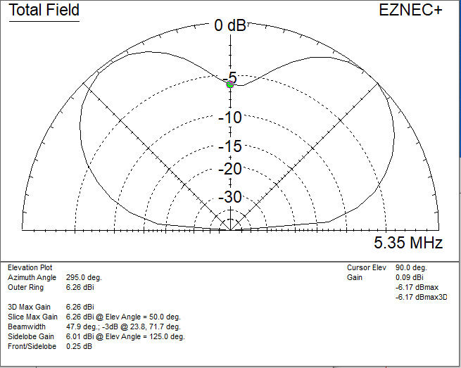
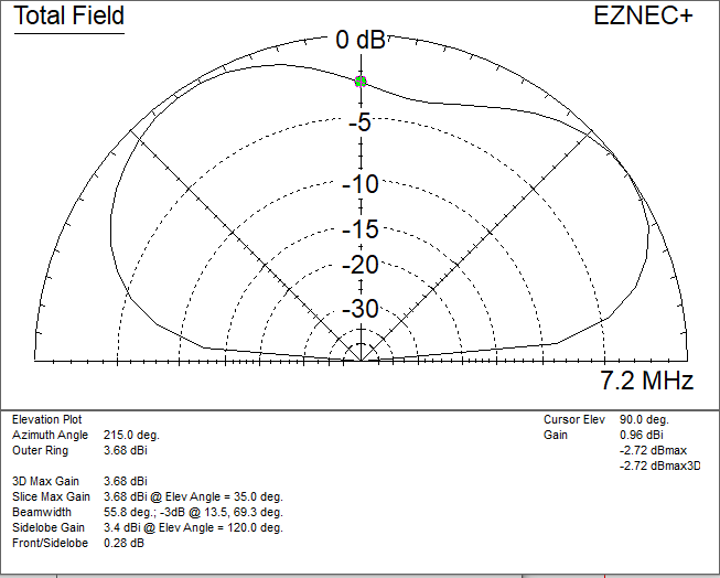
Sample patterns for a 30m (100 ft) sloping wire with the far end 10m (30 ft) off the ground. This is less than 1/4 wavelength on 160m, so is somewhat of a compromise antenna with a low feedpoint impedance and a lot of vertically polarized radiation, but it seems a reasonable length in many cases.
sample patterns for an inverted L
This model is 10m (30 ft) high and 40m (130′) long. That improves performance on 160m, but the pattern is has an overhead null on 40m because the wire is 1 wavelength long.
monoband operation
The simplest such antenna is simply a mostly horizontal wire 1/4 wavelength long. There will be some vertically polarized radiation, but it can provide a good match without needing a tuner. Such a wire can be clipped to an HF mobile mount, or even to a VHF 1/4 wave whip, as long as it has a good ground connection. (Mag mounts do not work well.)
Longer wires will work somewhat better, up to 3/4 wavelength or so, where the pattern starts breaking up and you may get an overhead null. A 3/4 wave wire often can be used without a tuner, or with a tuner that only matches up to a 3 : 1 SWR.
For the inverted L, there will be vertically polarized radiation from the vertical wire, but especially if the top is longer than 1/4 wavelength, it should still work well. The vertical wire can be supported by a light weight mast, and the far end can slope down towards the ground if necessary.
multiband operation
The radiation pattern of these wires breaks up into multiple lobes when they are 3/4 wavelength or longer. A 1/4 wavelength wire for 160m is 1 wavelength on 40m. Fortunately, there are ways to use the same wire on 160m through 40m by bending the wire. Let’s look at several options: in each case, I’m providing an overhead (“bird’s eye”) view of the wire. The feedpoint position is marked with a circle: this can either be sloping or with an added vertical portion (like the inverted L). What is important is the shape of the wire in the horizontal plane. Of course, these dimensions can be cut in half if you only need coverage for 80m through 40m.
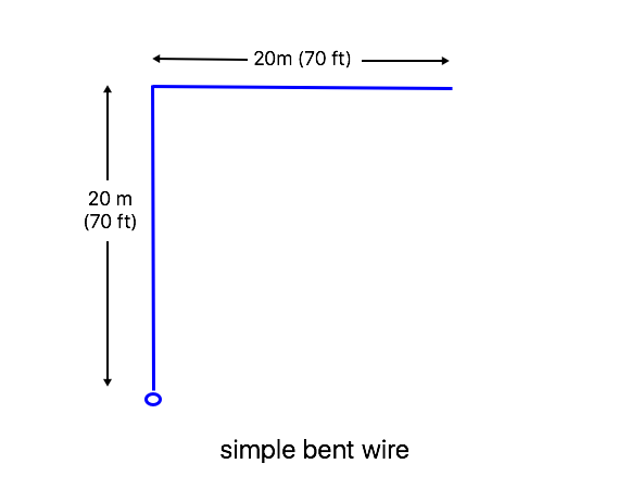
simple bent wire
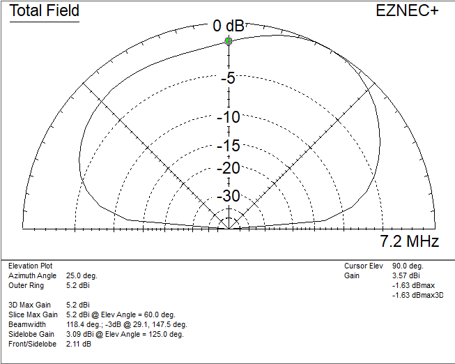
The ends of the bent wire can be elevated with a vertical feed wire, or at ground level with the wires sloping down. In the latter case, the wires can form two of the guys for a single support mast. It is about 1/4 wavelength on 160m, so it has high current in the vertical wire, giving some vertical polarization, but should provide adequate performance. That also means that the wire length is close to a multiple of 1/2 wavelength on 80m and 40m, which may be outside the range of some tuners: you can make the wire somewhat longer or shorter as needed to allow the tuner to match it on all bands of interest. The precise dimensions are not critical.
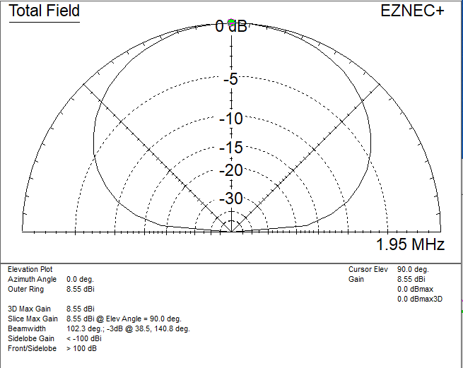
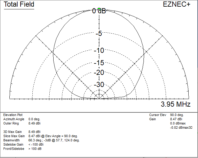
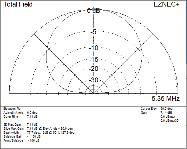
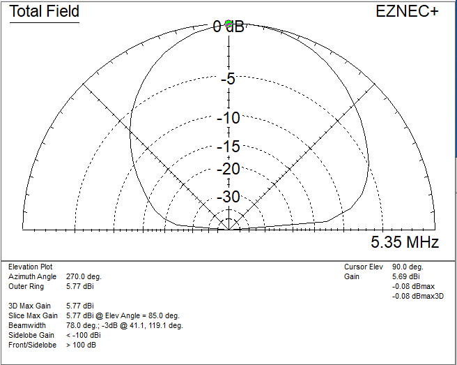
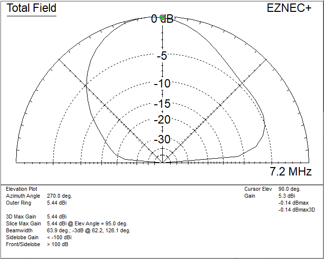
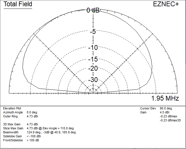
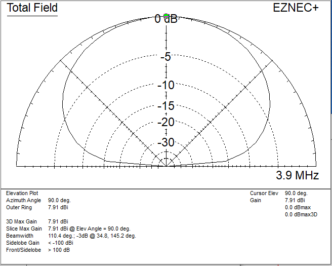
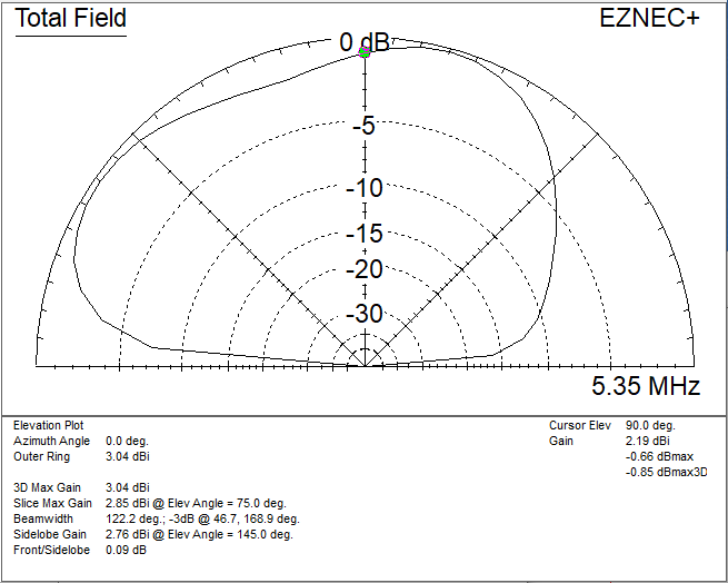
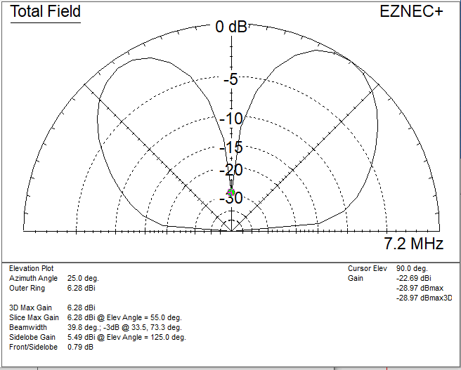
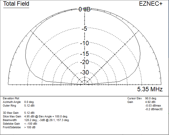
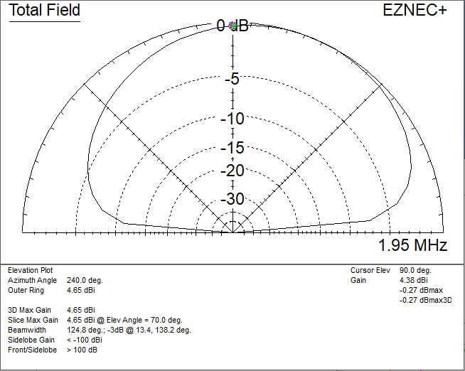
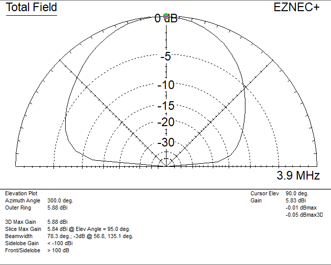
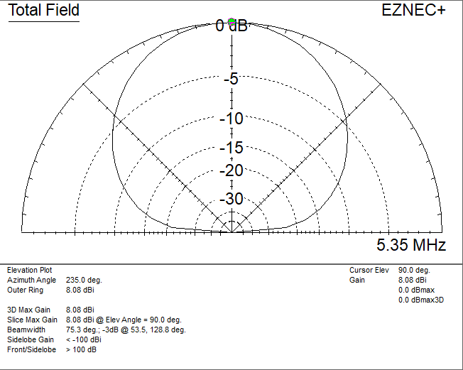
Patterns for the simple bent wire at a height of 10m (30 ft), with vertical wire down to feedpoint at ground level.

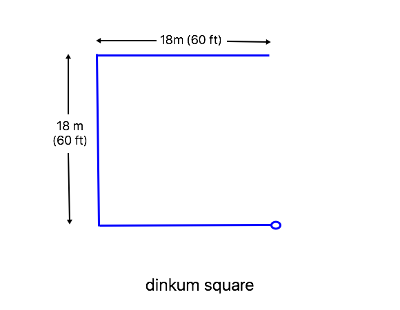
dinkum square
The dimensions for the Dinkum Square are about the maximum for NVIS operation on 40m, and the pattern gets a bit lumpy. Smaller sizes will work – dimensions are not critical (as long as the tuner can match it). Again, the ends can be at ground level, and if it is made a bit shorter you can angle the end wires to serve as guys for the two supports for the middle wire (with just two additional guy ropes on the opposite side.)
These patterns are for the antenna at a height of 10m (30 ft), with a vertical wire to the feedpoint at ground level. These dimensions have more vertically polarized radiation on 40m, where the vertical feed wire is 1/4 wavelength.
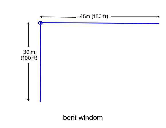
bent Windom
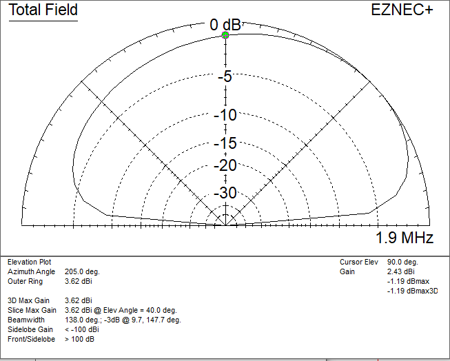
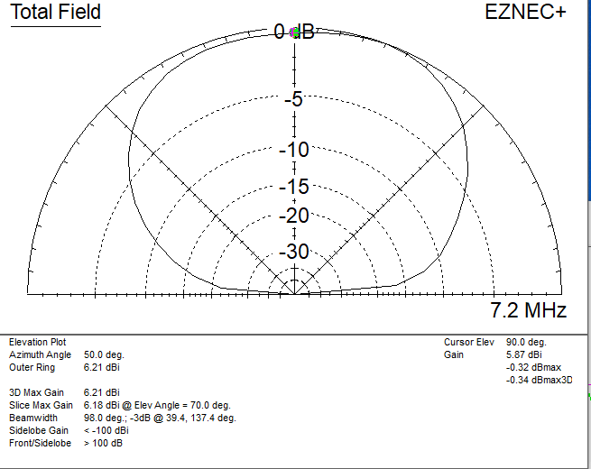
A traditional single-wire-feed Windom for 160m can be bent at the feed point as shown to give NVIS radiation on 160m, 80m, 60m, and 40m, although, again, the 40m pattern is a bit asymmetric because only the short end carries significant current. The feedpoint impedance is very close to a high impedance point, but the dimensions can’t be adjusted too much to maintain the proper operation on the higher bands.
These patterns are for the antenna up 10m (30 ft), with a vertical feed wire to ground level.
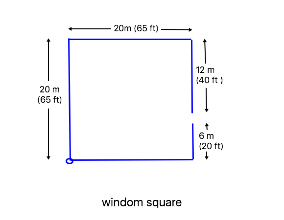
Windom square
The Windom can be bent further into a square to save space, with similar limitations. On 80m, this is the equivalent of a full wave loop, while on 60m it is a 3/2 wave loop.
Patterns are for an antenna height of 10m (30 ft) with a vertical feed wire to ground level.