Antennas for Field Day
last updated 23 December 2024.
Quick links:
A BEGINNER’S GUIDE TO FIELD DAY
FIELD DAY ANTENNA SELECTION GUIDE.
Field Day is an annual ARRL operating event that encourages emergency preparedness by giving hams the opportunity “to learn to operate in abnormal situations in less than optimal conditions.” Generally it involves setting up stations “in the field” (where there is not an existing station) and trying to work as many other stations as possible, using emergency power. It is one of the largest ham operating events in the world based on the number of participants.
In the context of this website, I’m using Field Day as an example of portable operating where antenna performance takes a higher priority over other factors such as setup time, weight, or size. Large clubs may set up multiple towers and beams, and run up to 20 or more stations at the same time, and participants are allowed 24 hours beforehand for setup. This might be similar to some DXpeditions or temporary contest operations. Site selection can be important. Sometimes it may also be a social occasion, with many participants sharing a meal.
On the other hand, there are many one or two person entries, possibly operating out of a backpack from a mountain top, or enjoying a family picnic outdoors. Locations vary from snowy tundra to farms, forests, deserts, or tropical islands. Some groups are focused on a high score, some on having a fun time outside playing with radios, and some take it as a great opportunity to experiment with different antennas. So Field Day antennas can cover a wide range of topics, but let’s start with some general principles.
Advance Planning
Location considerations
Geographic location makes a big difference for Field Day. Most stations are in the US and Canada, though there are participants from throughout North and South America, and operators from the rest of the world can be contacted as well. But looking at the density of participating stations, the epicenter is somewhere around the center of the Eastern half of the United States.
Stations in the Eastern portion of the US will have lots of single-hop signals (massive QRM), and antenna performance might not be as important as good filtering on the receiver. In the Central US and the Great Plains, there will be lots of strong signals to the East, but also some Western stations that may call for reversable beams to help alleviate the QRM. West Coast stations will find most of their contacts are to the East, and more directive beams may be useful, while lower angles of radiation are also important. Stations in Alaska, Hawaii, Guam, or South America will have more limited openings over longer distances, and it will be more difficult to be heard through the noise (especially if stations in the continental US are using beam antennas pointed in a different direction).
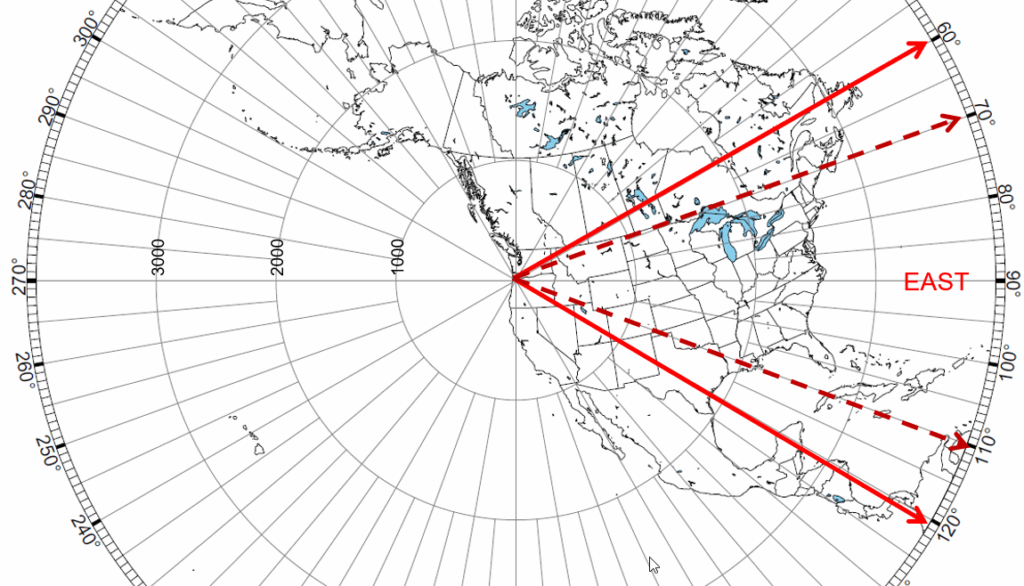
So your location will impact the required azimuth and elevation angles where you want to focus your signals, and your antennas should be considered accordingly. I find the azimuthal maps from NS6T convenient for planning.
I’ve operated most of my 40+ Field Days from Oregon, California, and Alaska, on the West Coast of the US, so I will often use that as an example. And usually by myself, or with a relatively small club having limited resources, so focused more on wire antennas rather portable towers. But often with tall trees available.
Site selection
There are several aspects of site selection that are important, including accessability, permissions, facilities, fire danger, shade, usable area, and the presence of inconvenient plants and animals. From an antenna perspective, the most important aspects are the availability of trees for antenna supports, and ground slope in the directions where low angle radiation is needed. While trees can be helpful, a dense forest may make it more difficult to install antennas. When trees aren’t available, then other supports will need to be provided: ground sloping down in the target direction will give better low angle radiation with low mast heights. An exception is when the site is close enough to salt water to make use of vertical polarization.
Altitude by itself is not a good predictor of low angle radiation: how the slope of the ground affects the reflected wave is more important. If you have a flat area with a steep drop-off in the desired direction, the ideal antenna placement will be close to the edge (less than about twice the antenna height), or even slightly down the slope, to maximize the effect. It may be worthwhile running the HF Terrain Analyzer software for a potential site to better understand the optimum antenna height and placement. (With a steep slope, it is quite possible for an antenna to be too high to be effective.)
When a large number of stations are relatively close, within 2000 km (1200 miles) or so, the angle of radiation isn’t as important, and modest antenna heights will still do well. But given the relatively sparse ham population of much of the inland Western US, our average contact distances have often been over 3000 km ( 2000 miles) on some bands, and planning antennas for low angle radiation becomes more important.
Propagation forecasts
I often find it worthwhile to check the propagation forecasts beforehand. From here in Oregon, the far East Coast of the US generally takes two hops, while the next row of closer states may be more reliable on single hop paths. Sometimes a band will open to a particular area for a relative short period of time. Bands such as 15m can also change quickly, and catching an opening can help to boost the QSO count. On the other hand, if 15m or 10m isn’t likely to open due to current ionospheric conditions, it might not be worthwhile installing antennas for that band, but focusing on improving antennas for the lower bands instead may be more productive.
Antenna Choices
Gain vs. Beamwidth
Many of the higher gain antennas suitable for low heights result in a narrow radiation pattern. It is worthwhile considering the trade-off that this involves in the number of stations one can work. My calculation from here in Oregon is that beamwidth of 40 to 60 degrees, centered on due East, will include most of the participating stations. Remember that antenna beamwidth is typically specified at the 3 dB points: we can still work closer stations outside that beamwidth where signals are stronger.
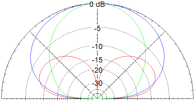
Achieving much gain without narrowing the beamwidth too much is not always a simple task, however, For example, a standard half-wave dipole might have a gain of 8.4 dBi and a half-power beamwidth of 86 degrees. That is wide enough to cover a lot of short contacts to the sides. Using a full-wave dipole (“two half waves in phase”, like a 40m doublet used on 20m), gives about 1.8 dB additional gain, but narrows the half-power beamwidth to 55 degrees. Stretching the dipole further to an extended double Zepp (EDZ, or 2 x 5/8 waves) gives 3 dB over a dipole, but the beamwidth is only 37 degrees, which limits the ability to work stations off the main lobe. Achieving gain by stacking antennas maintains a wider beamwidth, but requires more height to focus on low angles. Perhaps even more important is the beamwidth at 10 dB down: for a dipole 1/2 wavelength high, maximum radiation is at a vertical angle of about 30 degrees, and at that angle, radiation off the ends of a half wave dipole is down less than 10 dB from the main lobe, allowing contacts in all directions. The full wave doublet is down 20 dB off the ends compared to the main lobe, and the -10 dB beamwidth is 106 degrees: that means that signals are down more than 10 dB over a significant area off the ends. The EDZ has a -10 dB beamwidth of 66 degrees, so signals are down more than 10 dB over nearly 2/3 of the compass.
In practice, more casual operators often are happy working the stronger stations with less QRM, which in our case tend to be more off the sides of a narrow beam pattern, and the lower gain antennas are preferred. More serious operators often can work more stations with a higher gain antenna, and make up for the loss of stations off the sides. Depending on the operators, it may be worthwhile to have two different antennas: we might use a beam pointed East, and a dipole for North / South coverage.
There are some techniques for rotating wire antennas, but it isn’t as convenient as rotating a beam on a tower.
Simple Stations
For a relatively simple station, especially with lots of stations at short hop distances, antennas don’t need to be elaborate to make lots of contacts, and it may not really matter too much what type of antenna you use, as long as it is reasonably efficient. A dipole actually isn’t a bad antenna: I have to admit that, the more I have used dipoles for Field Day, the more I have realized that some of my other antennas haven’t really worked much better. Multiple dipoles (such as a combination of a 40m element with a 20m/80m dipole), or other simple multiband antennas such as the OCFD, G5RV/ZS6BKW, and doublets, should provide good results and be easy to set up. An end-fed wire of about 40m (130 feet) can work well with the far end pointed in the desired direction. The radiation patterns will shift around on the higher bands, and watch for feedline losses at high SWR, as well as tuner losses, with some popular antennas.
One of my favorite antennas is a horizontal 80m loop. I specifically use a square configuration fed in the West corner, as that gives me a major lobe due East on all bands (above 80m), and side lobes North and South to cover California, Washington, and British Columbia and surrounding areas. This requires 4 trees, and more space and planning to install. Others have had good results with different shapes.
Longer Distance antennas
Achieving low angle radiation (at least with horizontal polarization) generally requires either sufficient height or sloping ground in the desired direction (or both). Broadside arrays compress the pattern vertically, but generally require at least 15m (50 feet) of height on 20m to achieve significant gain, which is approaching the maximum height that I can throw a rope over a tree branch by hand. (A bow and arrow, or a compressed air cannon, can go higher.)
At this point, many of the antennas will be monoband types, though some of the double rectangles can be fed in the middle element with balanced line and used on at least 2 bands.
A vertical rectangle, such as a 50 ohm full wave loop for 20m, or double rectangles for the higher bands, helps to lower the angle of radiation, as long as it is high enough in the air. (The gain is in addition to that for the added height.)
Especially from one edge of the continent, directional antennas of various sorts are quite practical. Wire yagis and quad arrays can be hung from a rope “boom” stretched between two trees. The inverted vee yagi has a higher effective height, but a delta loop beam may be easier to install because the side ropes don’t have to extend out as far. We have used a 20m 5-element delta loop for a couple years, which gives better signals into the Eastern states, but the pattern is narrow enough that we tend to miss many of the West Coast stations, so we might need two antennas. One station in Maine (Northeast corner of the US) uses a 3-element 40m wire yagi pointed southwest for short hop paths, because there are very few stations in the other direction.
In the Central States, having a directional antenna that can help to reduce QRM from one direction or the other can be very helpful: this could be a switched reversible array rather than using a conventional rotator.
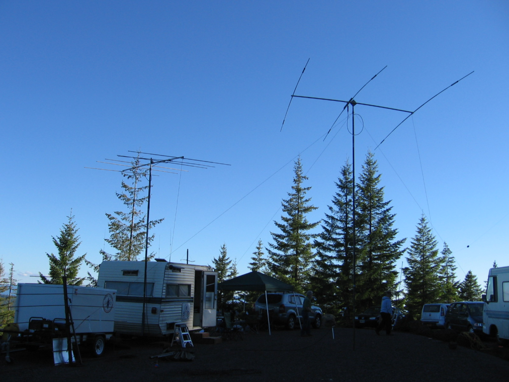
Conventional aluminum yagis are quite practical at heights to 10m (32 feet) or so using sectional masts, although weight becomes more of an issue for longer boom lengths. We regularly put up a short tri-bander (TA-33jr, shown in the opening photo of this page) with 3 people. (This takes practice. Put the mast up first by itself, get the guy ropes adjusted, then take the mast down, add the antenna, and put it back up.) Because the antennas are temporary, designing yagis with smaller / lighter elements and booms makes it easier to put them up, or use the mast to support a boom with wire elements. While 10m (32 feet) is not particularly high for low angle radiation, combining it with some ground slope can give good results. A light rope tied to one end of the boom will serve as a rotator (these can be seen on the 6m and triband yagis in the opening photo).
Vertical Polarization
You might think that vertical polarization would be ideal for low angle radiation, as it doesn’t require as much height as for horizontal polarization. Oregon has mostly volcanic soil with low conductivity, and when we have set up a vertical it didn’t do as well as the dipoles. But we often have plenty of trees to hang from antennas from. If the horizontal antennas are limited to lower heights, a vertical may have more of an advantage.
Vertical polarization can provide very good results, however, in conjunction with soil of good conductivity, and especially over salt water. Perhaps one of the best Field Day antennas I ever used was in the islands of Southeast Alaska, where a daily tidal difference of 6m (20 feet) was not uncommon. The only antenna I had was a Zepp-fed 40m (130 foot) wire, but I found a location where I could hang the feedpoint up 15m (50 feet) in a cedar tree hanging over the tide flats, then at low tide I walked out and tied off the end of the wire to a rock with a long rope, with the end of the wire pointing southeast. When the tide came in, I had a sloping long wire over salt water. With 2 watts SSB from a dying battery, I didn’t make a lot of contacts, but perhaps the most memorable were breaking pileups for KG4 (Guantanamo Bay) and KZ5 (Canal Zone). In the process, however, I forgot to watch the incoming high tide, which reached the back of the log where I had my station set up, and I nearly went Maritime Mobile.
To help you think about options, check out the FIELD DAY ANTENNA SELECTION GUIDE.
Other Antenna notes
I’ve tried a number of different Field Day antennas over the years. Some worked well, some didn’t. Here is my experience with several of them. Overall, many don’t seem that much better than a dipole.
End-fed long wire, 40m (130 feet) with a manual tuner. Worked OK. Direction of maximum radiation changes with frequency, but works reasonably well from the West Coast with the free end pointed East toward the most distant stations for the higher bands, giving broadside coverage North/South on the lower bands. (Worked great sloping over salt water, though!)
End-fed long wire, 200m ( 600 feet), sloping down a hill. Very poor, partly due to the fact that it sloped down the hill, and partly because the pattern was too narrow due to the length.
Vee beam with sloping 56 m (185 foot) legs. This had the feedpoint at about 10m (32 feet), with the legs sloping down and tied off 2 m (6 feet) above the ground. Each leg could be rotated individually to optimize the beam for various bands and directions. Tunable as a dipole down to 160m. Sounds great, worked OK. Sloping legs reduced the average height of the antenna – might have worked better if the legs were horizontal. Didn’t seem any better than many simpler antennas that took less space.
HF yagi. I have a triband TA-33jr (shown in the lead photo), along with light 2-element 15m and 3-element 10m monobanders, and often borrow a 6-element beam for 6m, that we put on 9-10m (28 – 32 ft) sectional masts. These can be installed by 2 or 3 people fairly easily once the antennas are assembled. Larger beams (4-el on 20m) have been used by welding a custom bracket to mount them on the side of an existing telephone pole. From here on the West Coast we generally just point them towards the East Coast and don’t bother with rotators, but in other situations manual rotation may be useful (mounting the beam on a rotator sleeve with a rope tied to one end of the boom makes a simple “Armstrong” rotator).
80m full wave horizontal loop. This worked well, but was more work to install, and requires more supports in the right places. Reasonable SWR using 4 : 1 balun at feedpoint, or feed with ladder line to a tuner. Very good multiband antenna.
40m doublet fed with ladder line. Worked 40m / 20m / 15m. Had trouble getting it to tune on 20m some years, depending on the exact length of the ladder line. Not quite as good as the big loop, but easier to install. Very slightly better than a dipole on 20m, similar on 40m and 15m. Replaced by dipoles and coax feed, which eliminated the tuner. Would be better if backed up with reflectors for 20m and 40m (as would the dipoles that replaced it.)
40m 2- and 3-element quads. Another great idea that didn’t always work as well as I had hoped. Actually, we used a 2-element quad (wooden spreader with wire elements) for many years and it worked well, as it was high enough off the ground on a hilltop, but those hanging from ropes between shorter trees suffered from lack of height. With delta loop elements, try to keep the bottom wires at least 6m (20 feet) off the ground.
80m 2-element quad. This might have worked well if I could get the reflector fixed, but the wires were passed over tree branches instead of being held up with ropes, and I ended up standing on a ladder with my arms stretched in opposite directions, each holding one end of the reflector wire and no way to pull them closer to join them. Again, low height was a limitation for longer distances. I also learned not to try to tune a big wire loop with a dip meter when another station nearby is transmitting. Actually, the driven element worked well enough by itself.
40m 200 ohm delta loop (point down). While nearly as long as a dipole, and slightly less gain, this antenna worked well because of the wide SWR bandwidth, so it didn’t need retuning if it didn’t get installed exactly as modeled. One version used a 4 : 1 balun, the other a quarter wave of “zip cord” (around 105 ohms) as a matching section. Very good monoband antenna.
Wideband 80m dipole using computer ribbon cable. Worked about as well as a dipole, of course, but covered the whole band with under 1.5 : 1 SWR. Particularly good for SSB across the 3.6 – 4.0 MHz range.
G5RV. This isn’t necessarily a bad antenna, but it didn’t work very well on 80m SSB (3.9 MHz) the one time I tried it. This might have been the lack of a balun and resulting ground losses from common mode current, losses in a long feedline with high SWR, or they were trying to use the band too early in the evening, before the D-layer absorption had dropped and/or other stations had migrated down to that band. Would be best with balanced line to a tuner rather than the hybrid coax feed system if used on bands other than 40m and 20m, or with a relatively short coax.
15m Folded Bruce curtain hanging from a fire lookout tower. Another good example of youthful enthusiasm and energy. We started with an 8-element curtain, but had been given the wrong tower height, and cut it down to 6 (about 23m or 75 feet tall) to make it fit. But we couldn’t hear any Field Day stations: it was totally useless. With all the US stations crowding the band, the strongest signal was an A6 working a station in France. Now, there may be times when that would be an ideal antenna response, but this Field Day was not one of them.
40m Bobtail Curtain. This was strung up on a hilltop Field Day site, fed with a tuner at the bottom of the center wire (covered with a plastic dish pan to keep it dry). It seemed like a good idea, but we never used it because the other 40m antenna worked well enough. However, when the 20m beam failed, we used the Bobtail to keep that station on the air, and it actually worked fairly well.
Quick links:
A BEGINNER’S GUIDE TO FIELD DAY
FIELD DAY ANTENNA SELECTION GUIDE.
Other useful links:
Videos page: setting up a sectional mast or a portable dipole, throwing a rope over a tree.
General notes on portable antennas
Simple construction of wire antennas
Construction of wire loop antennas
Masts and other antenna supports (including trees)
How to use a throwing bucket to put a rope over a tree branch