the original “fan dipole”
last updated 8 March 2022
Around 1991, an article in QST had a drawing of multiple half-wave dipoles on a common feedpoint, and referred to it as a “fan dipole”, because that was the shape the wires made. Since then, this has been a popular name, even when the wires are parallel rather than fan-shaped. Unfortunately, this tends to obscure the antenna that had already been known by that name for half a century, which has some useful attributes, including the ability to cover the entire HF spectrum with an SWR under 3 : 1.
So let me introduce the original “fan dipole”.
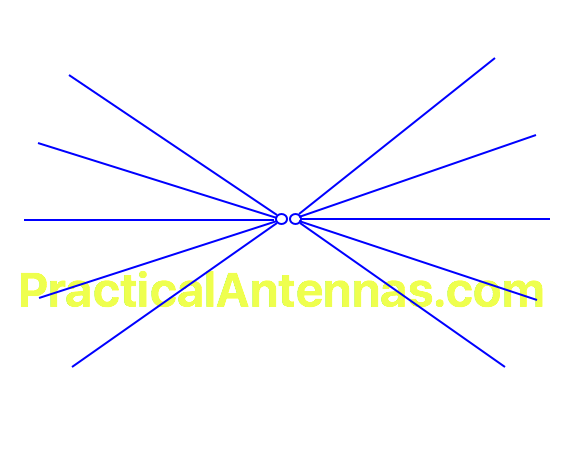
It is relatively simple – multiple wires, all the same length spread out in a fan on both sides of the feedpoint. What’s the benefit of the added wires? Check out the SWR curve:
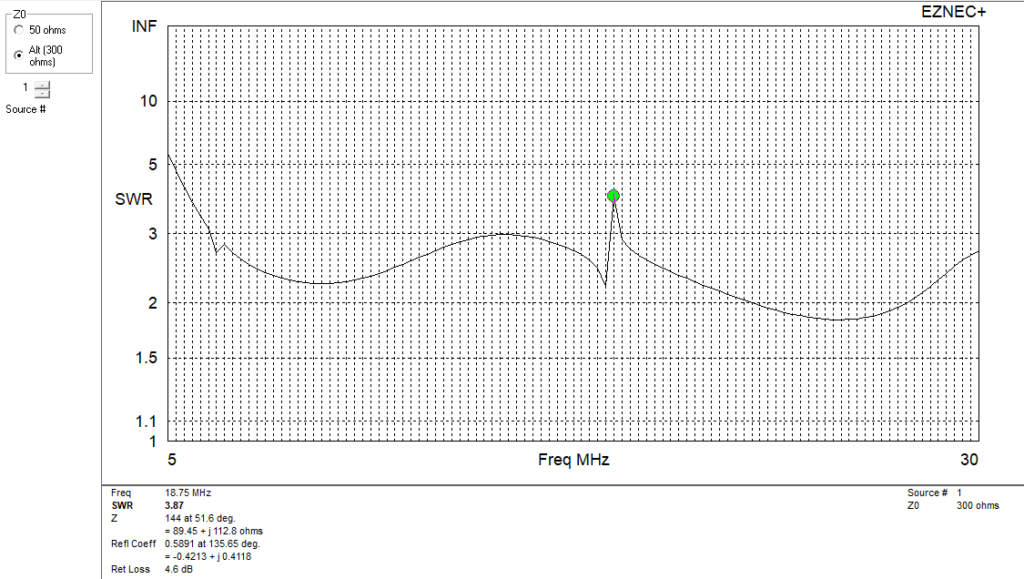
If your HF radio has a built-in auto-tuner that matches a 3 : 1 SWR, this antenna works from 40m through 10m. (That blip at 18.75 MHz doesn’t affect the 17m band, and may be a side effect of my model.) Using more wires gives a flatter curve. Adjusting the angle of the wires optimizes it for different feedpoint impedances. Even at 5 MHz, the SWR is low enough that coax losses shouldn’t be an issue, and a little bit more tuner capacity (or making it a bit longer) will provide coverage of 60m. In many cases, feeding such an antenna with a 4 : 1 balun will work well enough, and that extends the SWR curve on the low frequency end.
And this is without any lossy resistive loads, which are common features of many other wideband antennas.
derivation and alternate versions
A fan antenna using a flat metal surface rather than individual wires is 2-dimensional version of the biconical (“two cones”) dipole, which can also be built using discrete wires. A cone angle of 40 – 45 degrees should give a feedpoint impedance around 200 ohms, or 20 degrees for a 300 ohm antenna (such as a 4 : 1 balun with 75 ohm coax). The antenna height above ground affects the impedance, so some experimenting may be required. The antenna can also be installed as an inverted vee from a single center support.
Commercial versions like the Granger series using more wires in a triangular cone are rated to cover 1.6 – 30 MHz with an SWR under 2.5 : 1.
An 80m version using just 3 wires on each side of the feedpoint, with the center wire strung between two trees to support the feedpoint, and the two side wires sloping downwards, can cover the 3.6 – 4.0 MHz portion of the 80m band.
There are many other possibilities, but this shows why we want to remember the original fan dipole. For that reason, this is the antenna I mean when I use the term “fan dipole”.