5 Element Delta Loop
last updated 10 May 2022
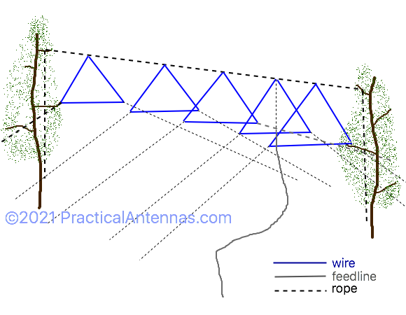
This 20m wire beam antenna was designed for Field Day use, where it was strung between two trees. It is an example of what can be done with a bit of creativity. The design can be scaled for other bands. This is one example of a wire quad antenna.
requirements
Let’s start with the requirements: I assumed a boom height of about 15 m (50 ft), although it works well at other heights. We had plenty of space between trees – at least 50 m (160 ft), so we could have used more elements, but for Field Day we had a target half power beamwidth of 40 to 60 degrees with the antenna pointed due East, which was the limiting factor. Of course, that assumes that your trees are aligned in the desired direction.
design decisions
There are two common methods for making such wire beams: using either delta loop elements or inverted vee yagi elements, supported by a rope boom strung between two trees. At lower heights, the inverted vee yagi designs have a higher effective height above ground, and may be better for low angle radiation. The downside of the yagi designs is that the support ropes for each element are longer. The delta loop design was chosen because we had sufficient height available (and favorable ground slope in the desired direction).
The next step was to review a number of designs for 3 to 8 element quads and yagis from the work of W4RNL and others. I particularly liked the 4- and 5-element 6m quad designs from G0KSC, as they gave good performance across the band. When scaled to 20m, the 4-element quad had 10.5 dBi gain on a 10 m (34 ft) boom and a 56 degree half power beamwidth in free space. The 2 : 1 SWR bandwidth was 320 kHz, and 230 kHz at 1.5 : 1 or better, which is adequate for the SSB portion of the band.
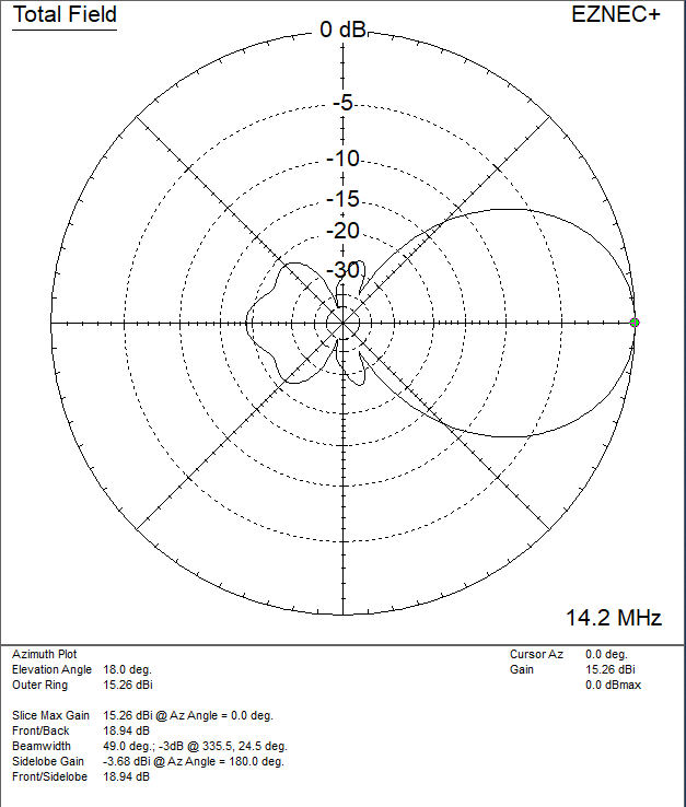
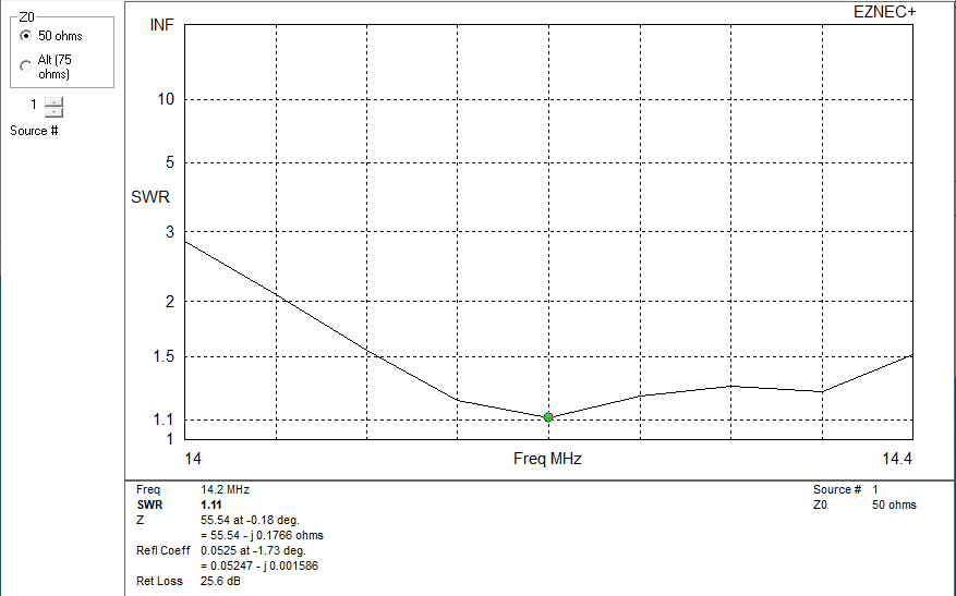
The 5-element quad used a 20 m (60 ft) boom, with 11.2 dBi gain and a 52 degree beamwidth. SWR bandwidth was 450 kHz at 2 : 1, although my initial version had an SWR around 1.5 : 1 for much of that range. But clearly it would cover enough of the band.
Once I decided on the initial designs, I converted them from square elements to delta loops. I don’t pretend that I captured all the fine details of the originals in the process. However, the delta loops permitted some adjustment of the loop shapes to tailor the feedpoint impedance, and the resulting antennas gave good results. (The original version of the delta loop was closer to 75 ohms.)
Is it worthwhile using 5 elements instead of 4? Probably not, to be honest. It would have been much easier to put up 4 elements on a shorter boom, especially when we had to string it among the trees. But sometimes it is important to stretch people’s imagination of what is possible for portable antennas, so we went with 5 elements. I’ve added the 4-element dimensions at the end of the article for those who want to try it, although it probably could use a bit more optimization.
Then I modeled the antennas over ground, rather than free space, and did some hand optimization. I rounded off the dimensions to convenient units, and made all the delta the loops the same height, adjusting only the width of the bottom of the loop for the individual elements. I did change the element height a couple times in the process of getting a 50 ohm feedpoint impedance.
final design
This is what I ended up with:
dimensions
These dimensions are for 1 mm wire (AWG #18) bare wire. Insulated wire probably will need to be a little longer.
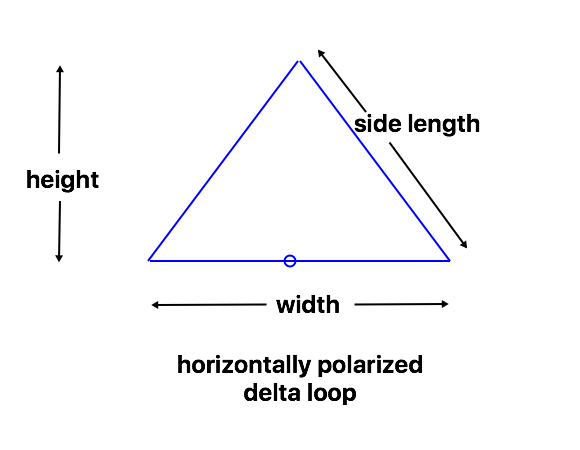
| element | height | width | side length | spacing from reflector |
|---|---|---|---|---|
| reflector | 4.88 m (16 feet) | 9.08 m (29.8 ft) | 6.66 m (21.9 ft) | |
| driven element | 4.88 m (16 feet) | 8.63 m (28.3 ft) | 6.51 m (21.4 ft) | 3 m (10 ft) |
| director 1 | 4.88 m (16 feet) | 8.47 m (28.8 ft) | 6.46 m (21.2 ft) | 6.1 m (20 ft) |
| director 2 | 4.88 m (16 feet) | 8.17 m (26.8 ft) | 6.16 m (20.9 ft) | 11.3 m (37 ft) |
| director 3 | 4.88 m (16 feet) | 7.96 m (26.1 ft) | 6.29 m (20.6 ft) | 18.3 m (60 ft) |
construction
The boom is a length of rope, a little longer than the element spacing. I tied loops in each end to attach the support ropes, and a loop for each element.
The elements are bare, solid aluminum wire sold for electric fences. Other types will work, of course, but I had a spool of this wire. By using bare wire I didn’t need to calculate a correction for the insulation, and the wire is very light.
The elements were measured about 2 cm (1 inch) long, and the ends of the parasitic elements were twisted together to form a loop. The driven element was connected to the center insulator from my portable dipole kit. Then the sides of the triangles were measured and the wire bent in each corner, with a short loop of rope attached. These loops are left on the elements when the support ropes are untied.
The tops of the elements were then tied to boom with short ropes. For the driven element, I added a vertical rope from the boom to the feedpoint to support the weight of the feedline.
installation
First, make sure you have enough rope. In addition to the boom (which is left connected to the elements when it is rolled up), putting this antenna up at 15m (50 ft) requires the following:
- 2 support ropes over the trees. These need to be at least twice the height of the branch, plus enough length to reach the ends of the boom when it is stretched out on the ground. We used 60 m (200 ft) or more.
- 10 ropes for tying off the corners of the elements. I estimated 30 m (100 ft) for each: at least long enough to reach the ground so you can add more rope if needed. There is very little tension on these ropes, so they can be lighter than the main support ropes.
Lay the antenna out on the ground between the two supports and tie the support ropes to the ends of the boom. Separate the elements and attach the corner ropes to the elements. (You can leave them wound up at the moment.) Make sure you have the feedline connected!
Raise the boom up off the ground a little, to where you can still reach the bottoms of the elements. This is your opportunity to make sure that the elements are going to clear any obstacles. We had to move the boom so that the elements fit in the openings between trees. Then unwind the corner ropes and lay them out in the desired directions. Adding a little bit of weight to the ends (or having people hold them) may help to reduce tangles and confusion as the antenna is raised.
Raise the antenna to the desired height using the main support ropes. This is another opportunity to adjust the antenna position: in one case we were installing it over a building, and couldn’t move it into position until it was at full height. Of course, all the corner ropes have to be adjusted accordingly.
Then tie off the corner ropes, maintaining the shape and spacing of the antenna as well as you can. Fortunately, small variations don’t make a big difference in performance.
results
Actually, we made comparatively few contacts with the antenna.
The antenna worked as designed, with stronger signals from stations on the East Coast of the USA. But the antenna wasn’t a good match for the operators using it, who were used to making more casual contacts over shorter paths, with stronger signals and little background QRM. Now we heard a lot more stations all mixed together, and it was more difficult to find a clear frequency. I’m sure serious contesters would have done well with it, but we didn’t have any of those in our group.
In this particular situation, a dipole may have been a better choice.
This should have been considered at the Requirements stage. It isn’t the fault of the operators or the antenna, but rather a failure to consider how the combination would work. Next time we put it up, we will also have a second antenna available with lower gain and a wider beamwidth to work stations over shorter distances that aren’t in the main beam of the antenna.
addendum: 4-element version
For the record, here is my 4-element design on an 11 m (35 ft). It isn’t as optimized as the 5-element version, but manages over 14 dBi gain with the bottom of the antenna at 12 m (40 ft). SWR is under 1.5 : 1 across much of the band for either 50 or 75 ohm feedline.
| element | height | width | side length | spacing from reflector |
|---|---|---|---|---|
| reflector | 4.66 m (15.3 feet) | 9.33 m (30.6 ft) | 6.60 m (21.6 ft) | |
| driven element | 4.54 m (14.9 feet) | 8.96 m (29.4 ft) | 6.38 m (20.9 ft) | 3 m (10 ft) |
| director 1 | 4.42 m (14.5 feet) | 8.84 m (29 ft) | 6.25 m (20.5 ft) | 6.1 m (20 ft) |
| director 2 | 4.27 m (14 feet) | 8.54 m (28 ft) | 6.03 m (19.8 ft) | 10.7 m (35 ft) |