80m Horizontal Loop for Field Day
last updated 31 March 2023.
This horizontal loop (or “sky loop”) was developed for use on Field Day, with a specific site and radiation pattern in mind. Your requirements may be different, but the analysis process that lead up to it may still be of interest.
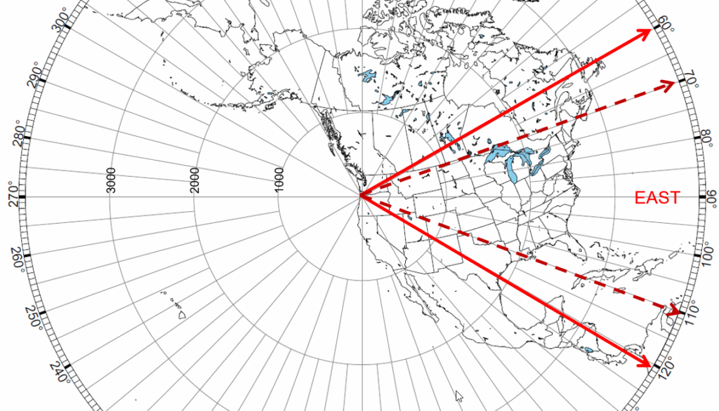
Most of my Field Day operation has been from the West Coast of the USA. From here in Oregon, most of the participating stations will be due East, +/- 20 or 30 degrees. There are, however, a lot of stations at relatively short (single hop) distances to the South in California, and to the North in Washington State and British Columbia, that are easier to work with less QRM. So, at least on the higher bands, I wanted a pattern with 3 main lobes at right angles. (A lobe to the West might help to work KH6, but they are strong when the band is open, so performance in that direction isn’t as important.) The most important bands for a good pattern are 40m, 20m, and 15m. (The pattern on 80m will be about the same, regardless of loop choice, and I’ll accept whatever pattern I get on 10m.) The available space limited me to 80m as the fundamental frequency.
Studying the Radiation Patterns for various loop shapes, the square loop fed in one corner (or “diamond loop”) seemed like the best candidate, with patterns like these:

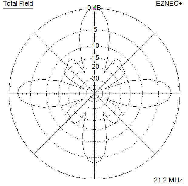
The directions of maximum radiation stay pretty much the same as I change bands. The 15m pattern is rather narrow, but has good gain: in practice, I expect it to be more spread out because I won’t get the shape exact when stringing it in the trees. Pointing the main lobe East gives me adequate coverage up and down the West Coast
My model suggested that a length of 86 m (282 ft) would be resonant near 14.15 MHz. In practice I had a 82.5 m (270 ft) loop of insulated wire already cut, so I used that. I started by tying small loops in the 3 corners for the support ropes.
The actual Field Day site was in a parking lot at the top of a steep slope that dropped down to the East about 15 m (50 ft) to a road, then continued dropping for another 200 m (600 ft) or so to the bottom of a valley. The first job was to verify the antenna alignment with a compass. The feedpoint would be at my station on top of the slope, the North corner would be in a tree about half way down to the road, and the East and South corners would tie to trees on the other side of the road, roughly level with my operating station.
I started out by laying out the wire on the ground, as well as I could. This did not work very well, due to brush along the NW leg, and the slope down to the road. Also the wire could not cross the road until we were ready to pull it up into the air, to avoid tangling any cars. Then I took my throwing bucket down to the road and put ropes over trees for the East and South corners, and got ready to raise the antenna. The South tree wasn’t ideally positioned, however, and didn’t pull the wire properly. So I untied the small loop in that corner and passed the wire through a floating insulator instead, allowing the rope to position itself along the wire as needed.
Now the only remaining problem was that I had about 2 m (6 ft) of extra wire on each end of the loop at the feedpoint, once I had it in approximately the right shape in the trees. I tied that off to my tent, and used the ends of the two wires as a balanced feedline to my tuner.
Actually I had several tuners available. The Johnson Matchbox and the MFJ-949 both matched the loop easily on all bands of interest. Out of curiosity, I wanted to know what impedance looked like with just a 4 : 1 balun, but the MFJ tuner didn’t have a “Through” option for the balun. I made one anyway, by putting a banana plug on the end of a short wire and connecting the balun to the COAX 2 antenna port instead of the “Single Wire” binding post. The SWR on 20m was about 2 : 1, but I went ahead and used the tuners for some additional filtering, since there were several other stations operating at the site, and the antenna picks up lots of RF across all bands.
It worked very well: I worked over 200 stations on QRP CW, and I’m not a serious contester. At night, when I wasn’t operating, the digital operator borrowed the antenna, and was very impressed. Part of the good performance was that it was over sloping ground in the target direction. And we had a clear path to the East for more than 80 km (50 miles). (A good site is perhaps more important than a good antenna!)
I used the antenna for 2 or 3 years, until I had an injured foot and couldn’t scramble up and down the slope to install it, so I put up a quick 40m doublet instead. At later sites the forest was too dense to put up the loop, so I used the doublet, or a set of dipoles.
Is the large loop right for your Field Day? First, consider the supports and space you have available: the loop is easiest to install when you can lay the wire out on the ground first. Then look at the patterns on the theory page to see which ones look suitable for your location. With limited space, you might find that a 40m loop would be a better choice. One of our other operators has put up an 80m loop several times for digital, using a triangle configuration (due to the available supports). It would appear to be pointed in the wrong direction, but he still reports that it seems to work well. The big loop is more effort to put up than some other options, and overload from other stations at the site needs to be considered, as well as available supports. But for a single antenna to work all bands 80m through 10m, it works pretty well.