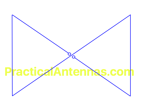
Bow-Tie Horizontal Loop
While a full-wave horizontal square loop has maximum radiation overhead for NVIS operation, the same loop used on its second harmonic has a null in the pattern. This design started as an effort to develop a loop with maximum radiation straight up on both 160m and 80m (or 80m and 40m). The temporary prototype worked so well, both on those and other bands, that it was left up as the main station antenna for 6 years (although I had to replace the wire twice).
The concept is fairly simple: a full wave loop for 160m is twisted into a folded dipole with two triangular ends. Each of those triangles is a full wave on 80m, and, as long as the wires cross in the center, the two loops are in phase on that band, giving a bit of gain over a single full wave loop.

Feedpoint impedance varies from around 100 ohms on 160m to 500 ohms on 20m, depending on height above ground and the exact shape of the loops. The version with equilateral triangles is the easiest to describe, and suggested as a starting point. (You can experiment with changing the relative lengths of the triangle sides to vary the impedance on each band, or using other shapes besides triangles.) I fed the original with a 4 : 1 balun at the feedpoint, and got a low enough SWR at some point on most HF bands that I could use the antenna without a tuner, but modeling suggests that may have been due to the low height, long coax, and possibly a poor balun design. However, the SWR should less than 4 : 1 at resonance, so losses due to SWR will be relatively low. The use of ladder line to a tuner in the shack may be a better option in some cases: in that case, the exact dimensions are not important. As with any large loop, the pattern on higher bands varies with a number factors, although often maximum radiation will tend to be along the long axis (through the midpoints of the end wires). A 80m / 40m loop will also have NVIS radiation on 60m, but the feedpoint impedance will be very high.
The original prototype was installed with the feedpoint on a 10 m (32 foot) mast, with the corners at 4 m (12 feet) high. This lowered the gain on 80m, as the end wires are responsible for much of the radiation, and it would be better if they were higher off the ground. (They can be higher than the feedpoint if practical.)
Expected resonances for a loop having equilateral sides of 28.5 m (93.5 feet), or a total length of 171 m (561 feet), are 1.75 MHz, 3.6 MHz, 7.0 MHz, and 14.1 MHz, and that seems to be a good size to keep the high order resonances close to the ham bands.
In some cases the frequencies may not have exactly a 2 : 1 relationship. This is often an issue with an 80m / 40m combination when it is to be used for SSB in the 3.8 – 4.0 MHz, which moves the 40m resonance close to 8 MHz. Looking at the current distribution, current is minimum in the center of the end wires on the fundamental frequency, and maximum on the second harmonic. This means that a coil or capacitor placed at that point will affect the resonant frequency of the higher band, but not the lower one. I adjusted the loop dimensions for 3.95 MHz and used coils of about 6 uH in the center of each end wire to bring the second harmonic down to 7.25 MHz. It does mess up the higher order resonances however. This isn’t necessary with ladder line feed.