A Band-Switched Antenna Tuner
last updated 26 December 2021
One complaint from those who use a manual antenna tuner in the shack is the need to readjust it every time they change bands. That’s one reason why automatic tuners are popular. But it really doesn’t need to take much time at all, as this tuner demonstrates. It can be use on receive, and has a bypass option for when it isn’t needed.
As always, I don’t expect you to duplicate this tuner, but it may give you some ideas to build your own to suit your own needs.
When I am using a fixed “permanent” antenna that requires a tuner for any length of time (my “permanent” antennas don’t always stay up as long as some of my “temporary” ones), I drag out this tuner and modify it accordingly.
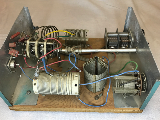
This is a simple L-network tuner, built around a 12-position ceramic wafer switch, with a series coil and shunt capacitors.
The switch selects a coil tap and capacitor as needed to match each band. For the higher frequency bands, one position is usually adequate for each band. For 80m and 160m, I may use several positions, or, in this case, I have a variable capacitor and an extra switched coil for tuning across those bands as needed.
To adjust it, I have a simple L-network using a coil and a variable capacitor that I use to obtain a match. Then I measure the capacitor (or read the markings off the scale if I am thinking ahead and mark it) and pick a near value fixed capacitor. In this iteration, I used old tube-era “postage stamp” mica capacitors, which are typically rated between 250 and 500V, and haven’t been a problem at 100W. (If the load impedance is over 1000 ohms, I might use two or more in series for a higher voltage rating.) For finer adjustment, a mica compression trimmer for each band could be used instead. Then, with that capacitor in the circuit, I experiment to find the tap on the string of coils that gives the best match. (The 4 coils shown are all connected in series, with the widest spacing used on the higher frequencies. I used what was I found in my junkbox. You probably could use a single air core coil like the one the yellow wire connect to, and a second wound on a ferrite toroid, if you wanted to make it smaller.)
The wafer switch is ceramic, and hasn’t been a problem yet at 100 watts, although it could be with extreme impedances. If you plan to run more power, you probably should upgrade the switch in addition to the capacitors.
With modern antenna analyzers, of course, you could just measure the load impedance on each band and use an online calculator to find the required inductance and capacitor. Odd values of capacitors can be made by connecting two in parallel or series. Due to stray inductance of the leads, the coil taps might not be exactly where you calculated them, but they should be close.
In most cases, I have obtained a match with a step-up configuration, or straight-through (which I always have as one position of the band switch). There is third wafer of the switch that isn’t currently used that could be used to select an input capacitor, or the existing capacitor wafer could be modified to switch the ground connections to the capacitors, in which case the capacitors could be on either the input or output side of the tuner. Depending on the antenna, sometimes multiple bands will match on a single switch position.
All of the settings will depend on your antenna and feedline, so I can’t give your specific values.
The photo also shows the blue 100k ohm resistor across the output for static discharge.
It does take some time to reconfigure the tuner when I put up a new antenna, but the time saved when changing bands over the course of a year is far greater. (And playing with antennas is fun, so it isn’t like the time is wasted.)
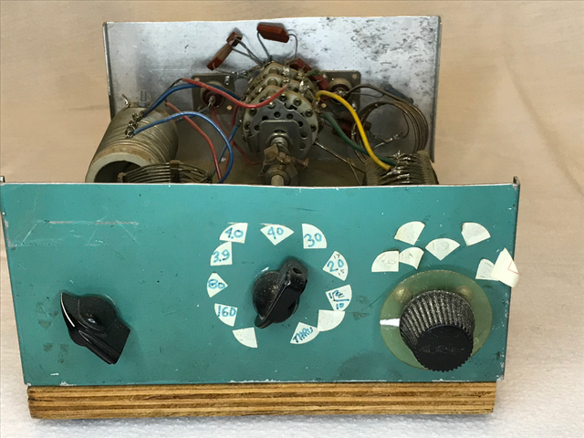
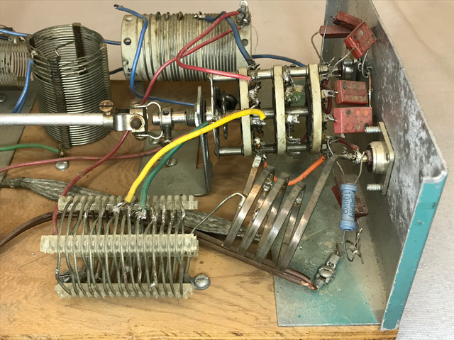
This side view shows the variable capacitor that tunes across the low end of 80m in the upper right, the switched coil for 160m in the lower right, and the mechanical construction. I didn’t have a chassis big enough, so I took part of a cover and cut it in half to make the the two ends screwed to a piece of wood, with a jumper wire connecting them. There is a metal bracket from something that supports the switch. The case could be smaller if I had a more organized set of coils.

Once I get it set up, operation is easy: I just turn the switch to the desired band. On 80m and 160m I might need to adjust one of the other controls, but the stickers on the front panel show me exactly where to set it, so there is no need to transmit or check the SWR. Until I put up a different antenna…