the Johnson Matchbox
last updated 12 December 2024.
The Johnson Matchbox is classic balanced tuner from the 1950s. It came in two sizes: one rated at 275 watts, and one at 1 kW. (Those numbers would be DC input to the final stage for AM modulation, and the PEP output values would be perhaps double that. The “275 watt” version is considerably more rugged than modern “300W” tuners.) Some versions had built-in SWR meters with a remote coupler.
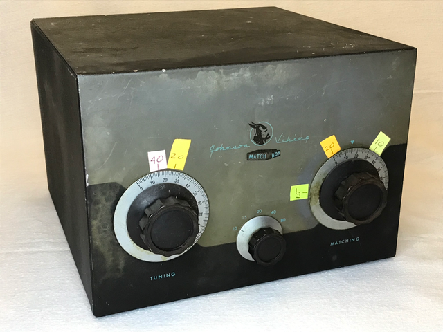
This is a link-coupled tuner with a balanced output (although a single-wire output was also provided). The secondary winding is tapped for the 5 pre-WARC79 bands, the secondary is tuned to resonance with the “Tuning” control, then a dual-differential capacitor across the output matches the impedance (“Matching”). There is a lot of interaction between the two capacitors, and I find it easiest to tune it with two hands, moving the two knobs simultaneously. That requires a bit of practice.
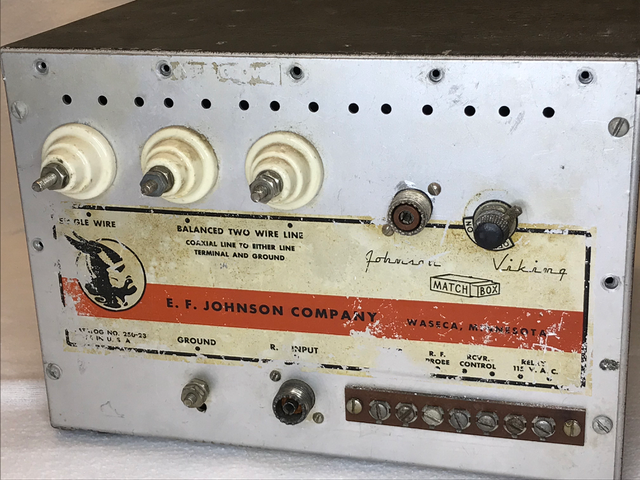
The back panel has two ceramic insulators for balanced line, one for single wire (far left) and an input jack. This unit has been modified with an output SO-238 connector, and a manual transmit/receive switch (upper right).
The row of screw terminals along the lower right are for the built-in transmit/receive relay. Designed in the time of separate transmitters and receivers, the stock matchbox routes the antenna through the tuner to the receive antenna terminal (second terminal from the left, where the label is worn off) instead of the coax jack marked “INPUT”. When 115 VAC is applied to the two terminals on the far right of the terminal strip, the internal relay switches the tuner to the transmitter input, shorts the receiver input to ground, and shorts the RCVR CONTROL terminals, that can be used to mute the receiver. Most units still in use have been modified for transceiver use by shorting around the relay or wedging it in the transmit position. Having exposed 115 VAC terminals on the back of equipment like this is dangerous, so modification is strongly recommended. An additional terminal is designed for use with an RF probe, but is not connected in my unit.
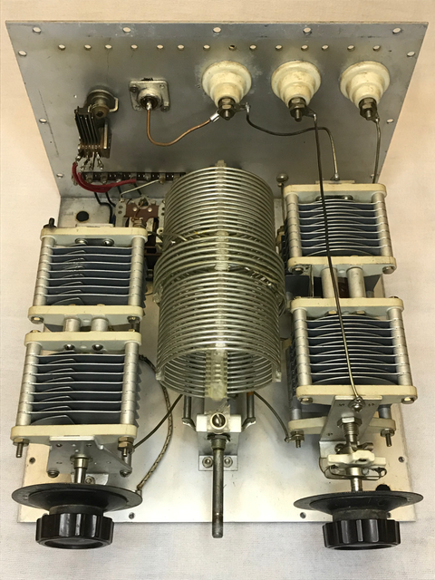
The inside photo shows the “tuning” capacitor on left, and the dual-differential “matching” capacitor on the right. The center shaft is for the band switch, which is under the main coil. The link coupling coil can be seen in the center of the main coil, and the taps for different bands are out of sight on the bottom of the coil.
The transmit/receive relay is in the far back left, and the switch above it on the back panel is a later addition (along with the coax connector wired to one of the balanced output terminals).
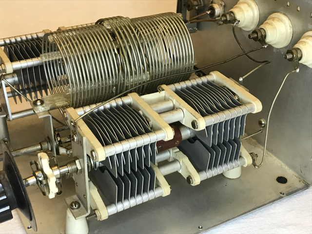
Each half of the dual-differential “Matching” capacitor has two sets of fixed plates sharing one set of rotating plates. As the shaft is turned, one side increases in capacitance while the other decreases. These are connected as capacitive voltage dividers across the secondary coil, permitting the output to be “tapped down” from the high impedance of the secondary winding.
While the Matchbox has a reputation of a “match anything” tuner, the matching range is actually somewhat more limited than many modern tuners, and it isn’t designed to cover the WARC bands. It is rated to match 25 – 1200 ohms for balanced lines. When using it on 20m with a 40m doublet, it was unable to get a good match with some feedline lengths. With the right combination of antenna and feedline length, however, it can work well across all 5 bands.
Reducing the number of turns on the link coil will improve the matching range somewhat. The full schematic, and a comparison with the improved Annecke antenna tuner from Germany with wider matching range, can be found in these articles:
Link Coupled Antenna Tuners from W4RNL
Johnson Viking Matchbox Upgrade from DJ0IP