factors affecting feedline loss
last updated 25 March 2025.
While it may not be difficult to understand that larger diameter feedlines have lower losses, it isn’t always clear what causes the losses in the first place, why the losses may be higher in cables designed for use at lower frequencies (like DC, AC power, or audio), or why open wire lines can have so little loss. So this article goes into a bit more depth.
There are two major contributors to the loss in a feedline: dielectric loss, and conductor resistance.
dielectric loss
Dielectric loss is due to the electric field passing through the insulating material between the conductors. Air (or a vacuum) is very good. Polyethylene or PTFE (Teflon®) are pretty good, and are used in most common RF cables. Mixing them with air (using a foamed dielectric) reduces the loss even further. For example, at 500 MHz, about 30% of the cable loss is due to the dielectric losses in solid polyethylene cables, while the value is less than 10% for cables using polyethylene foam insulation. (Foamed insulation in coax cable also permits the use of a larger center conductor for the same impedance, reducing conductor resistance.)
Generally, dielectric losses aren’t very important at HF and VHF frequencies. However, some plastics, such as PVC or nylon, may be rather poor, depending on the particular mix, and the higher losses may become noticeable even on 40m. This is often the primary cause of losses in using cables that aren’t designed for RF use, like those intended for power or audio applications. A good example is the loss plot for Belden 9264 coaxial cable, which is designed for audio use:
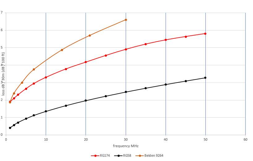
While this is similar in size to RG-174 (the red curve), and probably has even lower losses below 1 MHz, the loss increases relatively rapidly with frequency in the HF range due to the use of flame-resistant polypropylene insulation rather than polyethylene.
This is one of the important reasons for measuring the loss cables that weren’t intended to be used at RF: there can be some surprises!
conductor resistance
Most of the loss in RF cables below about 1 GHz is due to the RF current flowing through the conductor resistance. This resistance increases with frequency due to skin effect, where most of the RF current flows near the surface of the conductor, rather than in the interior. As the frequency increases, less of the cross-sectional area of the conductor is actually carrying significant current, and the effective resistance (often referred to at the AC resistance) increases over the DC resistance. This is why feedline losses increase at higher frequencies. (It is also why hollow tubes can be just as effective a conductor at AC as a solid rod of the same material.)
copper-clad steel (CCS) wire
But the skin effect also needs to be considered with some feedlines at low frequencies. Conductors made from copper-clad steel (CCS, such as CopperWeld®) have a layer of copper over a steel core. The steel is a very lossy conductor for RF due to the magnetic properties. As long as the copper layer thickness is at least 3 times the skin depth, the conductor should act like solid copper.
One of many online skin depth calculators is here.
At lower frequencies the skin depth increases. Below some frequency the copper won’t be thick enough to keep the RF out of the steel, and the losses will be higher than for a solid copper conductor of the same size. Typically, the total cable losses don’t actually increase as the frequency is lowered, but rather the curve flattens off, and the losses don’t drop as much as one might otherwise expect.
Let’s consider some sample numbers: using 3 times the skin depth as a guideline, these are the minimum copper thicknesses at different frequencies to keep losses to a minimum:
- 2 MHz: 130 µm ( 0.005 inches )
- 7 MHz: 75 µm ( 0.003 inches )
- 30 MHz: 36 µm ( 0.0014 inches )
- 100 MHz: 20 µm ( 0.0008 inches )
A common specification for CCS (CopperWeld®) wire is 30% copper, which means that the copper thickness is about 1/12 of the wire diameter. From that we can calculate the minimum size of solid CCS wire that we can use for any frequency without worrying about additional losses in the steel:
- 2 MHz: 1.6mm ( 0.063 inches, or AWG #15 )
- 7 MHz: 0.9mm ( 0.035 inches, or AWG #19 )
- 30 MHz: 0.4mm ( 0.016 inches, or AWG #26 )
- 100 MHz: 0.24mm ( 0.0095 inches, or AWG #30 )
(For BWG / SWG equivalent wire gauges, see this table.)
However, the problem gets worse when we use stranded wire rather than solid wire. That’s because the thickness of the copper on an individual strand becomes the thickness of copper on the outside of the combined wire, and each strand of a 7-strand bundle is 1/3 the diameter of the whole wire. So we can make a separate table for minimum sizes for 7-strand CCS wires:
- 2 MHz: 4.7mm ( 0.185 inches , or AWG #5 )
- 7 MHz: 2.7mm ( 0.106 inches, or AWG #10 )
- 30 MHz: 1.2mm ( 0.047 inches, or AWG #17 )
- 100 MHz: 0.72mm ( 0.028 inches, or AWG #21 )
Other configurations, such a 19-strand wire, will have an even thinner layer of copper.
Is this a problem? Consider that the stranded center conductor of RG-11 (a 75 coax cable the same size as RG-8 or RG-213) is 1.2mm. If such a cable were built using 7-strand CCS wire instead of copper, the loss figures at frequencies below 10m would suffer. Many smaller cables, such as RG-174, use stranded CCS for the center conductor ( 0.48mm, or AWG #24 ) for strength.
And those numbers assume the CCS is 30% copper: that’s not always the case. Inexpensive coax cables sold for cable TV usage, where losses in the VHF/UHF spectrum are most important, might have only a 20µm to 30µm copper thickness: the extra loss at HF doesn’t matter in that application, because the cable needs to be sized to work with the losses encountered in the UHF range.
We can also see the difference with commercial ladder line that uses stranded CCS conductors. Some common types use 1mm ( 0.04 inch or AWG #18 ) 19-strand CCS wire for flexibility. That would imply that the copper thickness is roughly 16µm ( 0.00065 inches ), leading to increased losses throughout the HF range compared to all-copper wires. This is mitigated somewhat because such cables typically have higher impedances, where conductor resistance is less of an issue.
This is not to say that such feedlines aren’t useful, just that the losses, especially on the lower HF bands, may be higher than expected, especially since some loss calculators may not account for them.
braid contact
For coax cable to work properly, the strands of the braid must make good contact to each other, so it acts like a continuous metal tube rather than many individual strands. One of most common modes of failure for coax cables is water leakage into the cable, which can cause oxidation of the copper. The braid can wick water up the cable to some distance from where it enters. (Unfortunately, higher losses will usually lower the SWR seen at the station end of the cable, so such problems are not always apparent.) Drying out the cable is rarely practical, and, even if it were, the corrosion between strands will remain.
When testing such cables using open- and short-circuit loads, the losses will often measure higher when the affected end of the cable is shorted.
When checking old cables, the braid under the outer insulation should still be shiny and clean. Otherwise, cut off the end of the cable until it is, as there isn’t any fix for it. (I have heard of technicians temporarily improving a cable by vigorously shaking and wiggling it, to try to wear off the corrosion between the strands. This is, at best, a partial and temporary fix.)
impedance
Because conductor resistance tends to be the major source of losses below the UHF range, reducing the current will reduce the power dissipated in the resistance. Thus a feedline with a higher characteristic impedance (higher voltage, lower current) can have lower losses. This is the major reason why open wire line has such low loss (although the losses are not necessarily as low as some historic data have claimed).
additional loss due to SWR
Operating a feedline at high SWR usually (but not always!) increases the losses. I’m going to cover this in a separate article. But for the moment, let me just give you a warning.
Any calculator that purports to give a “loss due to SWR” that only depends on the SWR value, is wrong.
Any calculator that purports to give a “loss due to SWR” that also factors in the cable type and length, is probably going to be wrong much of the time, but may give a useful estimate for cables over one wavelength long.
To be accurate, such a calculator must consider the actual complex impedance of the load.
back to:
adventures with small feedlines
related pages:
measuring characteristic impedance