2m yagi with a wood boom
last updated 13 December 2023.
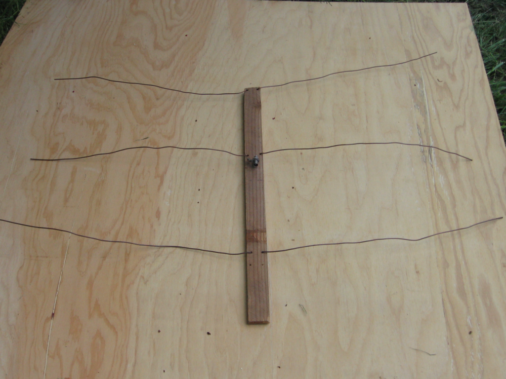
This is a ridiculously simple 2m yagi on a wooden boom, using common materials. It isn’t very rugged – it is intended for hand-held use, where the elements can be bent back into shape when needed.
But there is a story behind it: this very antenna was shown on Russian TV.

When my wife started competing in ARDF, she needed a lightweight 2m yagi. Most of my tape measure yagis were too heavy for her to hold for a long hunt. And some antennas didn’t have good balance, or she didn’t feel like she was getting good bearings.
So I brought out all of my yagis, set out a transmitter, and let her try each one. This is the one she said gave the best bearings, and felt best in her hand. So now it is her antenna, and I have to maintain it in exactly the original configuration, on pain of…. no, we won’t even think about it.
Actually, it is often the one I grab first when I need to take a quick bearing, or locate a source of interference. I have to replace an element every couple of years when a wire breaks, but that isn’t difficult. The wire elements are simply bent to fold against the boom for transport or storage.
The boom is flat wood (known as “lath”), about 4 cm wide and 1 cm thick ( 1 1/2 inch by 3/8 inch ), and long enough to form both the boom and handle. Mine is 60 cm ( 24 inches ) long, but this is a matter of personal preference, and you might want it longer, depending on how you hold it.
The elements are 2 mm ( AWG #12 ) solid copper wire, commonly used for wiring houses, with the insulation removed. (No, don’t try to remove it with wire strippers: use a knife to slice a thin strip of insulation off one side of the wire, down to the copper, and the rest will pull right off.)
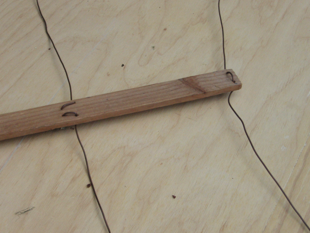
The elements are attached to the boom by drilling two holes side-by-side, and passing the wire through them. I find it easiest to fold the element into a U shape, pass both ends of the wire through the holes, then flatten the element. I start with the element a bit long, then trim it to the desired length after it is in place.
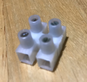
The driven element takes a bit more work, but not much. Each half of the driven element has two holes, lengthwise along the boom, as shown in the photo. The ends of the wires then connect to the coax. (I use a BNC connector, but you can use a terminal block to attach the coax if you don’t want to solder, as shown for the 2-element 2m quad.)
dimensions
There are several options.
The “official” set that I have to maintain on this particular antenna are:
| element | length mm | spacing from reflector mm | length ( inches ) | spacing from reflector ( inches ) |
|---|---|---|---|---|
| reflector | 1015 | ( 40 ) | ||
| driven element | 965 | 255 | ( 38 ) | ( 10 ) |
| director | 915 | 470 | ( 36 ) | ( 18.5 ) |
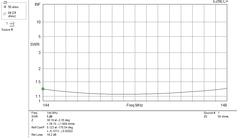
The SWR is about 1.5 : 1 across the first 2 MHz of the 2m band, and increases to just over 2 : 1 at 148 MHz. The extra wire between the feedpoint and the coax connector adds some inductance, so you might want to trim your wires for your desired frequency. This the SWR that my model shows:
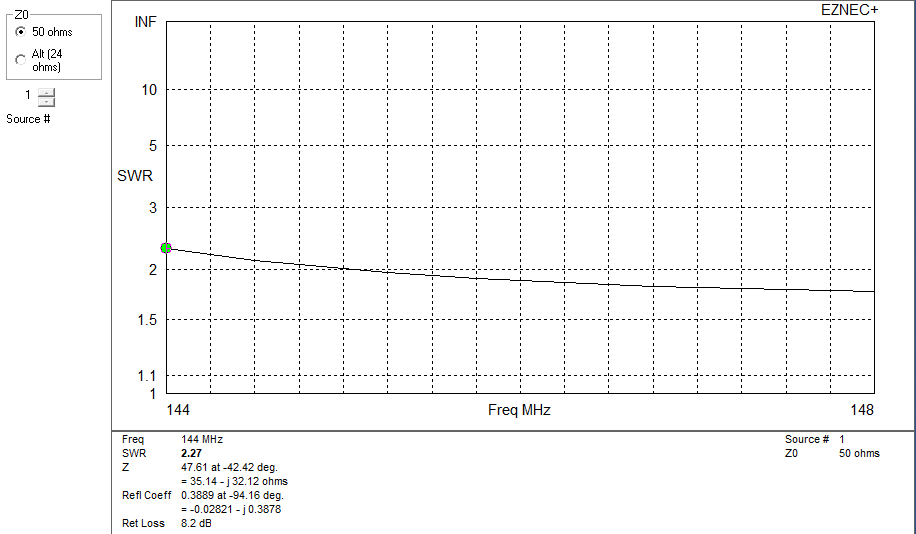
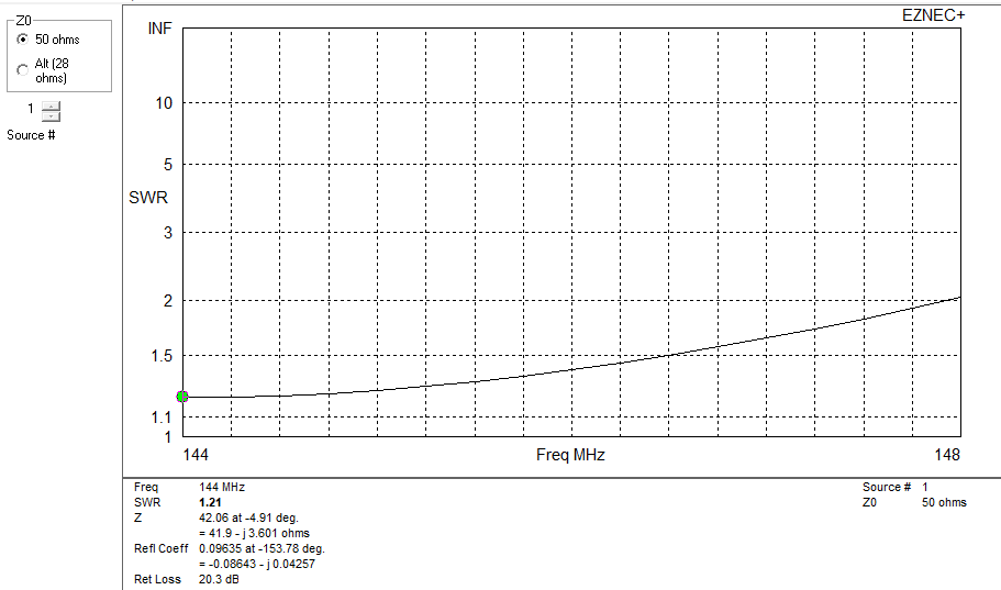
Increasing the driven element in the model by about 3 cm ( 1 inch ) to account for the extra wire makes the SWR curve look much better:
So cut the driven element a bit long and plan to trim it to account for how you have constructed the feedpoint.
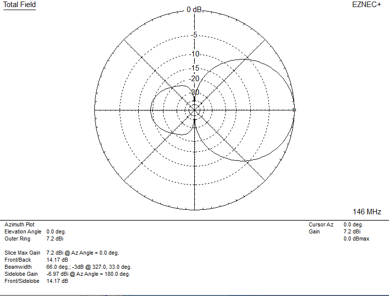
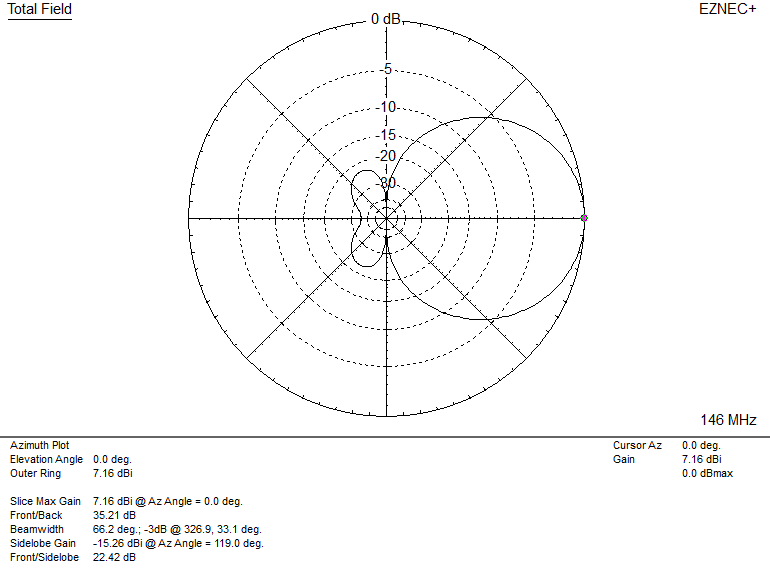
The pattern isn’t perfect, but quite usable. For horizontal polarization:
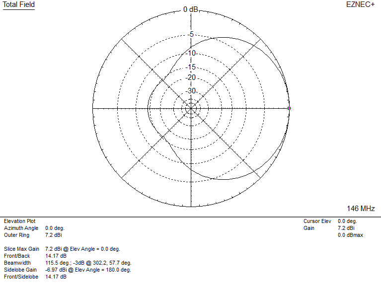
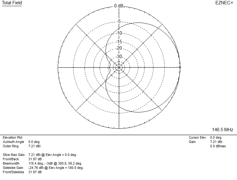
For vertical polarization:
Other dimensions can be used. Here is a set that makes the boom a bit longer, and improves both the SWR and Front-to-Back ratio, with about the same gain as the original:
| element | length mm | spacing from reflector mm | length ( inches ) | spacing from reflector ( inches ) |
|---|---|---|---|---|
| reflector | 1070 | ( 42 ) | ||
| driven element | 1000 | 250 | ( 39.5 ) | ( 10 ) |
| director | 930 | 500 | ( 36.5 ) | ( 20 ) |
Patterns and SWR curve for the modified dimensions. Again, you may need to adjust the length of the driven element based on your construction methods.


And the radiation pattern for vertical polarization at 146 MHz:
Of course, there are many other sets of dimensions that can be used with this construction method, but these are convenient lengths that give a reasonable 50 ohm match.