The Importance – or Not – of Antenna Resonance
last updated 28 February 2025.
One often encounters articles and comments about the advantages of resonant antennas.
Don’t believe them.
Now, this view isn’t totally false: it is, perhaps, built on bits of truth, but distorted by the improper or unclear use of words, some misunderstandings, and a limited vision of possible options. So to make sense of it, and to understand what is really important in antenna systems, let’s start by defining terms and looking at some examples.
Resonance
There are various definitions for “resonance”, or a “resonant” antenna at a given frequency. Generally it means that RF leaving the feedpoint and reflected from the far end of the antenna arrives back at the feedpoint with the exact same phase. (It could also be 180 degrees out of phase, which is sometimes known as “anti-resonant”, although that phrase is not used much in modern antenna discussions.) This happens only at specific frequencies related to the length of the antenna. When it does, then, at any feedpoint location along the antenna, the impedance is purely resistive.
For this purpose, I will define a “resonant” antenna to be one with a feedpoint impedance that, when expressed in the form R +/- jX, the X value is zero, or at least small enough not to matter.
What does this mean?
Or, perhaps more importantly, what does it NOT mean?
A resonant antenna does not necessarily have a low SWR. Antennas with a feedpoint impedance of 5 + j0 or 500 + j0 are resonant, by this definition, but either will have an SWR of 10 : 1 when fed with 50 ohm cable. And either may still be a useful antenna. Note, however, that one cannot have a low SWR when the load impedance has significant reactance. To have a low SWR on a cable with a characteristic impedance of 50 + j0, R must be close to 50 ohms and X must be close to 0 ohms. So, if there is no other matching in the system, having a low SWR means the antenna must be close to resonance, but the reverse case is not true when all the feedline has the same impedance as the SWR meter. Things get more complex when we use feedlines with different impedances.
Whether or not an “antenna” is “resonant” depends on where you draw the line between the antenna, the matching network (or “antenna tuner”), and the feedline. Let us look at some examples to see what this means.
5/8 wave vertical example
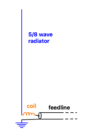
Consider the case of a 5/8 wave vertical for 14.25 MHz over a good ground plane, as shown in Figure 1. This would generally be considered a good antenna. Depending on the exact length and the element diameter, the feedpoint impedance might be 60 – j220 ohms, which clearly is not resonant. The SWR is around 18 : 1.
However, if we add a coil with a reactance of + j220 ohms (about 2.8 uH) in series at the feedpoint, it cancels the capacitive reactance, leaving 60 + j0 ohms, bringing the SWR down to 1.2 : 1, which is low enough for most practical purposes. Does this make it a resonant antenna?
That depends on whether we consider the coil as part of the antenna or not. We could put the coil in a separate box at the base of the antenna and call it an “antenna tuner”. Or we can attach the coil to the base of the radiator and call it a piece of the antenna. In one case the “antenna” is resonant, and in the other case it is not. But any difference between them is purely artificial, since the antenna works exactly the same in either case.
So any discussion about a “resonant” antenna being better than a “non-resonant” one is inherently starting on the wrong foot before anything else is said, and needs a better definition of the topic to be at all useful.
40m doublet example
Let’s consider another example: a 40m doublet that is 26 m (85 ft) long. The feedpoint impedance is about 200 + j490 ohms, so clearly not resonant. Then we will feed it with about 11 m (36 ft) of 300 ohm twinlead to a tuner, so the radio sees 50 ohms, as shown in Figure 2. Does it make a difference that the antenna isn’t resonant?
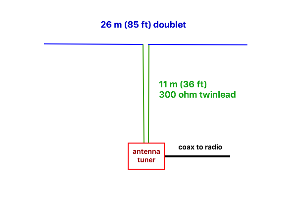
No, not really. Some might complain about the loss due to SWR in the twinlead, or the losses in the tuner. But if we look at it more closely, it turns out that the loss in the twinlead, even at an SWR of 6 : 1, is about the same as the same length of RG-213 coax when it is matched; certainly not enough to worry about.
What about losses in the tuner? Well, let’s look in side the box and see what sort of matching network we need. Open the lid, and… there is nothing there, just two wires connecting the coax to the twinlead. The combination of the antenna length and twinlead gives a perfect match to 50 ohms (better than 1.1 : 1, at any rate), and we don’t need a tuner at all (although a balun would be good practice). If we consider the wire part itself, the antenna is not resonant. If we consider the wire plus feedline as the “antenna”, (for example, if we buy a commercial G5RV or ZS6BKW antenna that includes the twinlead matching section) the combination is resonant (and has a low SWR). Now we are back to the same situation: depending on how you define the antenna, it could be resonant or not, but there is no difference between the two cases.
What actually makes a difference?
It isn’t about whether or not the antenna is resonant. The main problem is when the SWR is high (whether the antenna is resonant or not), the feedline losses can be much higher, particularly with coax. Adding an antenna tuner in the shack to provide a match for the transmitter doesn’t reduce the feedline loss between there and the antenna. Putting the matching at the antenna end of the feedline instead allows the coax to operate at a lower SWR, and eliminates the extra loss.
This might be what some hams mean by a “resonant antenna”, but the words are not precise enough for the statement to be correct.
Generally, the entire antenna system as a whole needs to provide a reasonable match between the transmitter (or, on receive, the antenna) and the antenna (or the input to the receiver). Modern receivers usually have enough gain to receive signals even when somewhat poorly matched, but transmitters may not generate their rated output power. As long as the losses in the antenna and feedline are not too high, that matching can be done anywhere in the system: it makes no practical difference whether the radiator by itself is resonant or not.
Perils of resonant antennas
Modern antenna analyzers make it easy to read the reactance of an antenna (even if some don’t indicate whether it is capacitive or inductive). This is useful in many cases, but isn’t always the best way to tune an antenna.
For most simple antennas, such as a half wave dipole, the purpose of adjusting the antenna is so that the transmitter sees a load impedance as close as possible to the value it is designed for. What is the best measure of how close the actual load impedance is to the target value? In the case where the design output impedance of the transmitter is the same as the characteristic impedance of the feedline, there is a common measure that shows just that: we call it “SWR“. If your transmitter is designed for 50 ohms, then using a 50 ohm SWR meter at the output of the transmitter indicates how close the load impedance is to 50 ohms. (This works even if the antenna is fed with coax with a different characteristic impedance, as long as the coax between the SWR meter and the radio is 50 ohms.)
That’s not to say that the resistance and reactance values aren’t useful for other purposes, but they aren’t needed for tuning an antenna. In the case of a half wave dipole where the wire length is the only adjustment, we generally start with the wire a bit long and prune off (or fold back) the ends until the frequency of lowest SWR is a the desired point in the band. Being able to measure the SWR curve across the band helps to confirm that we need to shorten the antenna instead of making it longer, of course, but SWR is sufficient. There is no guarantee that we will be able to tune the antenna to exactly 1.0 : 1 with only one adjustment (the dipole impedance varies with height above ground, among other factors), but the lowest SWR we can get is generally good enough.
When our antenna has two adjustments, perhaps the element length and a shunt matching coil, we can adjust them alternately to reduce the SWR at the desired frequency. We should be able to get the SWR very low, as long as we have enough adjustment range.
But with all those other numbers on a modern antenna analyzer, sometimes the simplest approach doesn’t seem sophisticated enough. Now many hams are trying to tune their antennas to achieve X = 0, rather than simply lowest SWR. This doesn’t always give the desired results…
Example: tuning a vertical
Consider the case of tuning a quarter wave vertical antenna for 20m. With horizontal radials and some combination of radiator diameter and height above ground, we might get a feedpoint impedance of 21 + j0 ohms at 14.1 MHz, the target frequency. The antenna is resonant at that point, and the SWR is 2.37 : 1.
One common quirk to note is that the SWR is not minimum at 14.1 MHz, but dips down to 2.35 : 1 at 14.18 MHz. This is because the antenna resistance varies somewhat with frequency, although not as fast as the reactance. If only the reactance changed across the band, then the SWR would dip at the resonant frequency. But the difference is smaller than the expected accuracy of most SWR meters, and not worth worrying about. In this case we can say that the minimum SWR is close enough to the resonant point for all practical purposes.
However, it is not always convenient to measure the impedance right at the feedpoint to the antenna. The person holding the meter might affect the antenna. So let’s be more practical and put a 1 m (40 inch) coax jumper between the antenna feedpoint and the analyzer.
Remember that, while the SWR remains constant along a length of feedline (ignoring losses), the impedance varies when the line is not perfectly matched. The SWR still reads 2.37 : 1, but the impedance the analyzer sees is now 25 + j19 ohms, just due to the effect of the short coax jumper cable.
Now, if the ham doesn’t understand this, and thinks he should adjust the antenna to be resonant where X = 0, he might assume that, since the reactance is positive (inductive), the antenna needs to be shortened, and removes 10 cm (4 inches) from the radiator. The analyzer shows impedance at 14.1 MHz is now 19.5 + j8 ohms, and the SWR has increased to 2.66 : 1. Cutting off another 10 cm (4 inches) gets it to 15.5 + j0 ohms, and an SWR of 3.23 : 1. He achieved X = 0, but the SWR is now over 3 : 1.
Meanwhile, at the antenna feedpoint, the impedance is now 18.5 – j21 ohms. The antenna is actually resonant at 14.52 MHz, and the SWR dip is 2.41 : 1 at 14.6 MHz. In practice it probably will still work as well as before, as long as the tuner will match values over 3 : 1. (Personally, I’d probably try to angle the radials downwards, or add a shunt matching coil at the feedpoint, to get a better match to 50 ohms, but those aren’t always practical.)
Other cable lengths will give different results, some of which can be quite odd.
The point is, if you are adjusting an antenna to resonance by looking for X = 0, then you must correct the measured impedance for the length of the coax cable, or take the measurement directly at the feedpoint. Some analyzers can be calibrated at the end of a length of cable, and there are convenient calculators that will calculate the correction if you know the length and type of the cable. On the other hand, simply centering the SWR curve in the 20m band doesn’t need any correction: it will give the right result with any reasonable length of cable.
BACK TO:
RELATED ARTICLES:
tuning an antenna with an antenna analyzer