wire yagis
last updated 15 February 2023.
While most commercial HF yagis are build using aluminum tubing, they can also be made using wire elements. The smaller size will reduce the available and bandwidth somewhat, but such antennas may be much more practical for temporary or portable operation. Common designs such as the Hex Beam, Spider Beam, and Moxon use a complete framework to support the wires, but if it doesn’t need to be rotatable (at least, not very quickly) then the ends of the wires can angle downwards and be tied off near ground level, with a great reduction in mechanical complexity.
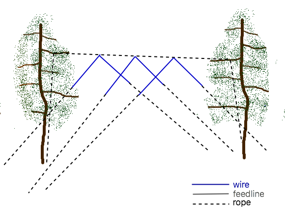
Shorter antennas, particularly the 2-element designs, may be supported from a cross spreader on top of a single mast, and rotated by untying and moving the bottoms of the ropes. Longer antennas can be hung from a rope boom between two trees. In this configuration, it is most convenient to arrange the elements as inverted vees, although horizontal elements might be accommodated with additional rope supports. And, once the rope boom is in place, little additional effort is needed to add more elements in whatever space is available, although the beamwidth of the resulting array and the alignment of the rope need to be considered.
At least at low heights, these yagis have an advantage in average height compared to a wire delta loop (point up) array hanging from the same boom. But at heights over 1/2 wavelength, the delta loop designs generally give more gain with a shorter boom.
Construction is relatively simple: start with a rope boom a little bit longer than the total antenna length and tie a loop in each end. Then mark the element positions on the rope along the remaining length. Cut the elements to lengths, tie a small loop in the center of each, and tie the loops to the marks on the rope boom using a short piece of rope or string. Make sure you mark which end of the boom has the director, so you get it pointing in the correct direction!
Then tie the support ropes to the loops on the ends of the boom, and individual ropes to the ends of the elements. Raise the boom into the air, then tie off the element ropes, trying to keep the wires mostly parallel. You can adjust the main support ropes to move the boom forwards or backwards to get the elements to clear trees if needed.
There are many different beam designs that can be used. I suggest starting with one that has a wide bandwidth, converting the elements one at a time to wires, then bending the elements to a vee shape, which will require a number of corrections to the original dimensions. One approach is to use K7MEM’s calculator for DL6WU yagis: although results won’t be perfect with small diameter wires, it may give you a good starting point for long arrays.
suggested dimensions
The following dimensions are modeled values using bare 1mm (AWG #18) wire. Insulated wire will need to be somewhat shorter, depending on the characteristics of the insulation, which may require experimentation.
They can be scaled to shift the SWR curve, and may not be fully optimized, but should work reasonably well. Solid aluminum wire for electric fences is lighter than copper, and available in large spools for large antennas. Heights are what seems “reasonable” for each band (assuming flat ground): changing the height affects the angle of maximum radiation, but not the element lengths unless is too close to the ground. The slope of the wires is (where practical) about 60 degrees from vertical, so the total length of wire + rope should be about twice the height of the antenna (if it is tied off at ground level).
These antennas are designed for 50 ohm feed, and a wide enough SWR bandwidth to cover much of the band, as well as being relatively tolerant of field conditions. The small wire and bent elements will reduce the maximum gain somewhat from what is possible with a conventional yagi. However, unlike a yagi built with aluminum tubing, the additional cost of adding another element is relatively low, especially when using a rope boom tied between two trees. So it may make more sense to use a longer beam than to try to squeeze higher performance from a shorter one. It is easy enough to add a shorted stub across the feedpoint to match lower impedance designs if higher gain is desired.
I haven’t provided dimensions for every possible band, but they can be scaled as desired.
2-element yagis
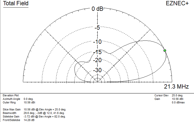
These 2-element wire yagis give about 3 dB gain over a horizontal dipole at the same center height.
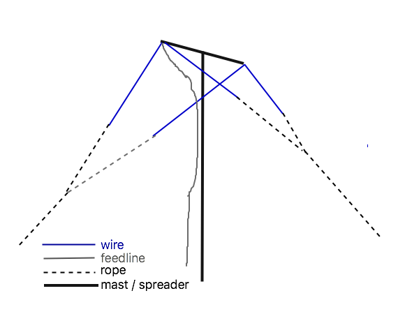
The ends of the wires are angled towards each other, so they can be connected to a common point (using about 1/4 wavelength of rope on the end of each wire) and then a single rope from there to the anchor point. That reduces the number of ropes that need to be untied to rotate the antenna if it is hung from a spreader on a mast. The elements can be tied out straight if desired.
Shortening the reflector increases the gain, lowers the feedpoint impedance, narrows the SWR bandwidth, and improves the front-to-back ratio (up to a point).
Note that the SWR bandwidth is not centered on the design frequency with these antennas. In each case, the SWR reaches 2 : 1 just below the bottom of the band (except for 40m, where it is about 7.025 MHz).
| band | center spacing m ( feet ) | nominal height m ( feet ) | driven element length m ( feet ) | reflector length m ( feet) | design frequency MHz | 2 : 1 SWR bandwidth kHz |
|---|---|---|---|---|---|---|
| 10m | 2 ( 6.5 ) | 6 ( 20 ) | 5.04 ( 16.53 ) | 5.25 ( 17.25 ) | 28.4 | 1500 |
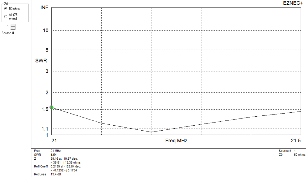
| 15m | 2.7 ( 9 ) | 8 ( 25 ) | 6.75 ( 22.2 ) | 7 ( 23 ) | 21.2 | 900 |
| 20m | 4 ( 13 ) | 12 ( 40 ) | 10.16 ( 33.3 ) | 10.52 ( 34.5 ) | 14.15 | 600 |
| 40m | 8 ( 25 ) | 24 ( 80 ) | 20.25 ( 66.5 ) | 21 ( 69 ) | 7.1 | 300 |

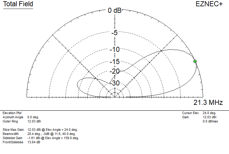
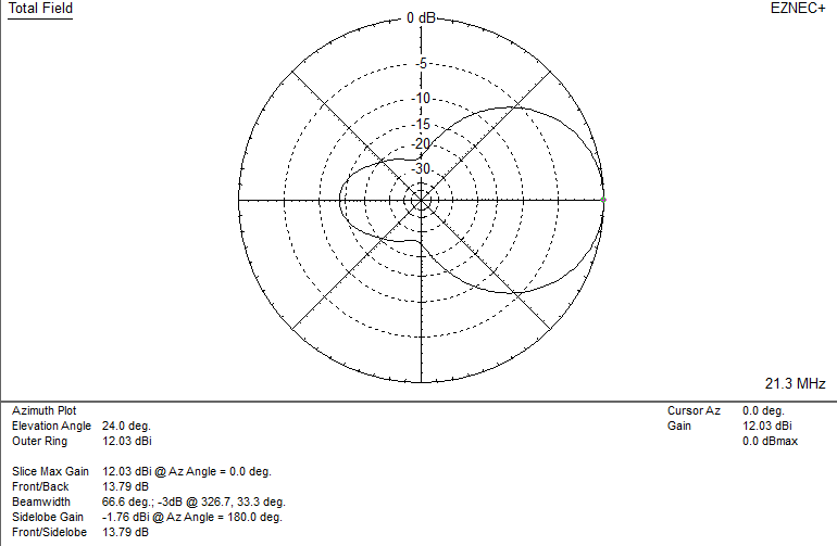
3-element yagis
I’ve included 3-element yagis here because they are traditional. But before you build one, look at the following 4-element yagis, which give better performance and a flatter SWR curve with a shorter boom length. That makes them more reliable for use in the field with less than ideal conditions.
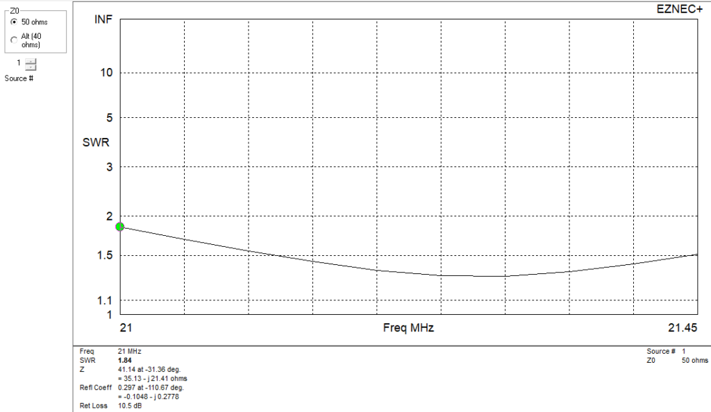
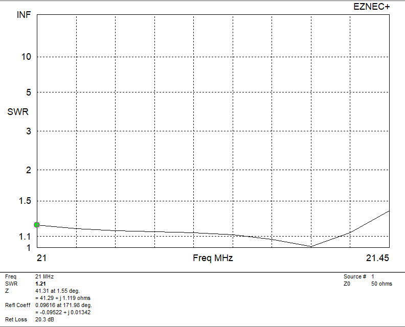
These 3-element yagis give about 1.5 dB gain over the 2-element versions. I’ve tried to give a reasonable 50 ohm SWR, but the feedpoint impedance tends to be around 40 ohms, and the SWR bandwidth is narrower. Equal spacing is used for the reflector and the director.
Higher gain is possible, with a more narrow bandwidth and the use of a shunt coil or shorted stub across the feedpoint for impedance matching.
| band | 10m | 15m | 20m | 40m |
|---|---|---|---|---|
| element spacing m ( feet ) | 2.5 ( 8.2 ) | 3.5 ( 11.5 ) | 5.25 ( 17.25 ) | 10 ( 33 ) |
| director length m ( feet ) | 4.84 ( 15.9 ) | 6.54 ( 21.5 ) | 9.8 ( 32 ) | 19.5 ( 64 ) |
| driven element length m (feet) | 5.08 ( 16.7 ) | 6.82 ( 22.4 ) | 10.25 ( 33.7 ) | 20.4 ( 67 ) |
| reflector length m ( feet ) | 5.25 ( 17.25 ) | 7.04 ( 23.1 ) | 5.27 ( 34.6 ) | 21 ( 69 ) |
| design frequency MHz | 28.6 | 21.275 | 14.175 | 7.15 |
| SWR bandwidth kHz | 1000 | 600 | 400 | 225 |
The elements can be angled towards each other to tie them off with a single rope, as was done with the 2-element designs. This decreases the gain slightly, but improves the front-to-back ratio.
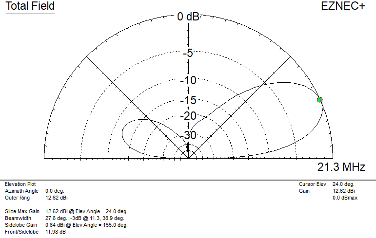
4-element yagis
With 4 elements it is possible to apply the OWA (Optimized Wideband Yagi) approach, with an element spaced close to the driven element to allow better adjustment of matching. That allows these antennas to be designed for higher gain than a 3-element yagi of similar boom length, with a low SWR across the band.
The SWR curve rises very steeply past the upper end of the band for these antennas. Keep that in mind if you are trying to scale them to other frequencies: the best approach is to scale them based on the highest frequency in each range.
Element spacings are measured from the reflector. Note that the SWR bandwidths are for 1.5 : 1 SWR, rather than 2 : 1 in the prior tables.
| band | 10m | 15m | 20m | 40m |
|---|---|---|---|---|
| reflector length m ( feet ) | 5.34 ( 17.5 ) | 7.20 ( 23.6 ) | 10.76 ( 35.3 ) | 21.3 ( 69.9 ) |
| driven element spacing m ( feet ) | 1.67 ( 5.5 ) | 2.25 ( 7.4 ) | 3.36 ( 11.0 ) | 6.75 ( 22.1 ) |
| driven element length m ( feet ) | 5.20 ( 17 ) | 7.00 ( 11.5 ) | 10.46 ( 34.3 ) | 20.70 ( 67.9 ) |
| director 1 spacing m ( feet ) | 2.45 ( 8 ) | 3.30 ( 10.8 ) | 4.93 ( 16.2 ) | 10.05 ( 33 ) |
| director 1 length m ( feet ) | 5.04 ( 16.6 ) | 6.80 ( 22.3 ) | 10.16 ( 34.6 ) | 20 ( 65.6 ) |
| director 2 spacing m ( feet ) TOTAL LENGTH | 4.53 ( 14.9 ) | 6.10 ( 20.0 ) | 9.12 ( 30 ) | 18.75 ( 61.5 ) |
| director 2 length m ( feet ) | 4.97 ( 16.3 ) | 6.69 ( 22.0 ) | 10 ( 32.8 ) | 19.8 ( 65 ) |
| design frequency MHz | 28.45 | 21.2 | 14.15 | 7.175 |
| SWR bandwidth @ 1.5 : 1 | 800 kHz | 650 kHz | 430 kHz | 250 kHz |
7-element yagis
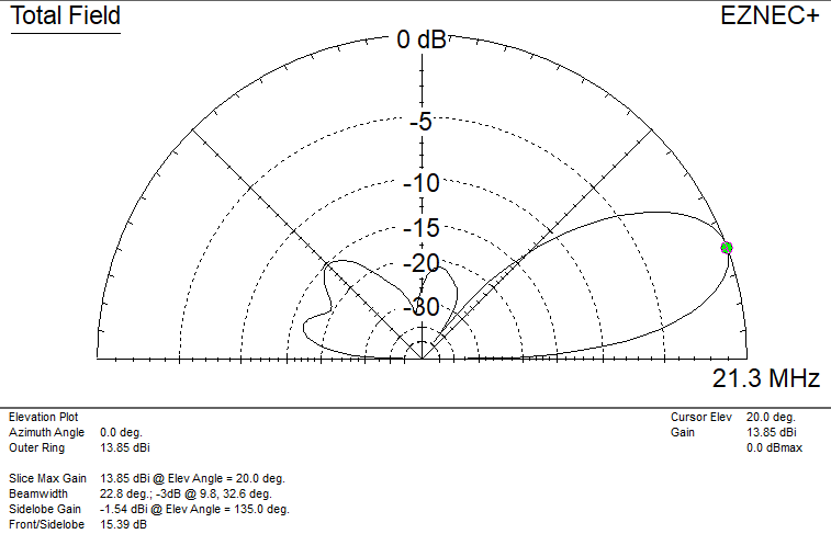
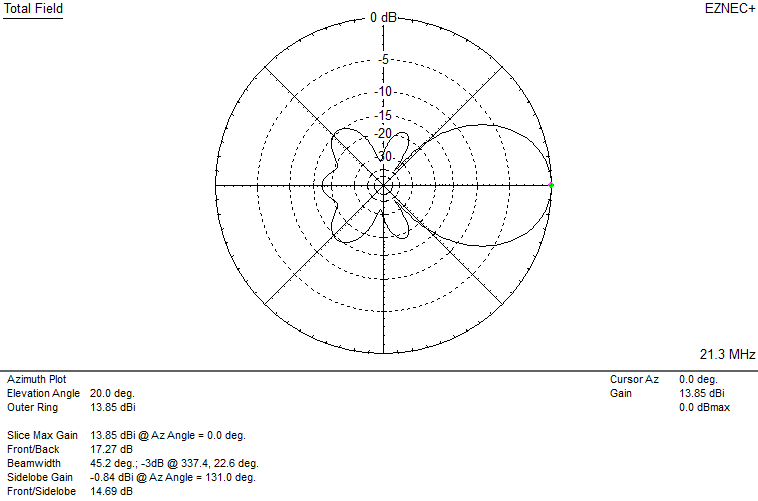
These beams have about 7 dB gain over an inverted vee at the same height by itself, and are based on an OWA design from the late W4RNL. The driven element and first director are relatively close-spaced, and I’d recommend spreaders between them especially on the higher bands. Total length is over 1 wavelength, with about a 45 degree half power beamwidth..
As with other designs, these can serve as a starting point for further optimization to improve SWR, gain, pattern, etc. And, while longer yagis are certainly possible, this seems like a reasonable limit for portable use.
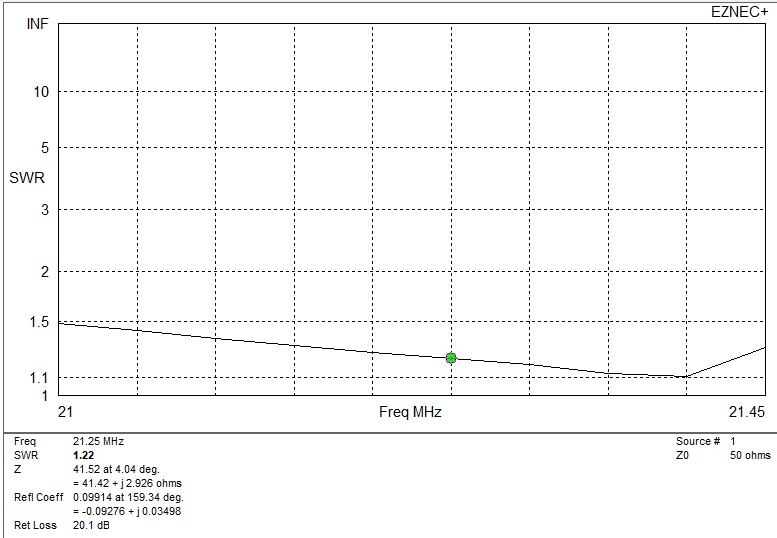
Again, spacings are all measured from the reflector, and the SWR bandwidth is given at 1.5 : 1, so the antennas cover nearly the whole band (except on 10m).
| band | 10m | 15m | 20m | 40m |
|---|---|---|---|---|
| reflector length m ( feet ) | 5.5 ( 18.1 ) | 7.42 ( 24.3 ) | 11.13 ( 36.5 ) | 21.84 ( 71.6 ) |
| driven element spacing m ( feet ) | 1.35 ( 4.4 ) | 1.8 ( 5.9 ) | 2.7 ( 8.9 ) | 5.3 ( 17.4 ) |
| driven element length m ( feet ) | 5.24 ( 17.2 ) | 7.04 ( 23.8 ) | 10.55 ( 34.6 ) | 20.8 ( 68.2 ) |
| director 1 spacing m ( feet ) | 1.65 ( 5.4 ) | 2.2 ( 7.2 ) | 3.3 ( 10.8 ) | 6.5 ( 21.3 ) |
| director 1 length m ( feet ) | 5.04 ( 16.7 ) | 6.82 ( 22.4 ) | 10.22 ( 33.5 ) | 20.08 ( 65.8 ) |
| director 2 spacing m ( feet ) | 3.6 ( 11.8 ) | 4.8 ( 15.7 ) | 7.2 ( 23.6 ) | 14.1 ( 46.3 ) |
| director 2 length m ( feet ) | 5.0 ( 16.4 ) | 6.72 ( 22.0 ) | 10.07 ( 33.0 ) | 19.78 ( 64.8 ) |
| director 3 spacing m ( feet ) | 5.55 ( 18.2 ) | 7.4 ( 24.3 ) | 11.1 ( 36.4 ) | 21.8 ( 71.5 ) |
| director 3 length m ( feet ) | 4.93 ( 16.2 ) | 6.62 ( 21.7 ) | 9.92 ( 32.6 ) | 19.48 ( 34.0 ) |
| director 4 spacing m ( feet ) | 8.35 ( 27.4 ) | 11.1 ( 36.4 ) | 16.7 ( 54.8 ) | 32.7 ( 107.3 ) |
| director 4 length m ( feet ) | 4.93 ( 16.2 ) | 6.62 ( 21.7 ) | 9.92 ( 32.6 ) | 19.48 ( 34.0 ) |
| director 5 spacing m ( feet ) TOTAL LENGTH | 11.65 ( 38.2 ) | 15.6 ( 51.2 ) | 23.4 ( 76.8 ) | 45.95 ( 150.8 ) |
| director 5 length m ( feet ) | 4.85 ( 16.3 ) | 6.66 ( 21.8 ) | 9.98 ( 32.8 ) | 19.6 ( 64.3 ) |
| design frequency MHz | 28.450 MHz | 21.225 MHz | 14.175 MHz | 7.175 |
| SWR bandwidth @ 1.5 : 1 | 600 kHz | 480 kHz | 350 kHz | 260 kHz |