Simple Construction of Wire Antennas
last updated 18 August 2023.
Building a Simple HF Dipole Antenna
A wire dipole is one of the easiest antennas to build, and the same methods can be used for most other wire antennas. By choosing the right materials, and not worrying about how other books show to do it, it can be quite easy and quick.
In this example I’ve chosen a variety of components to demonstrate both the build process and the range of different options. There is nothing special about these: I expect you will use other materials, depending on what you have available, but the principles are the same. I’ve included links to discussions of each of the components if you want to read more.
What you need
- Feedline with a connector at the radio end. Generally 10m to 20m (30 to 60 feet) is a reasonable length for the coax attached to an antenna. It might need a connector on the antenna end also, depending on your choice for a:
- Center insulator. This provides strain relief for an electrical connection between the feedline and the antenna wires. Some center insulators contain baluns, but the construction process is basically the same.
- Wires. These need to be cut to length for the desired frequency band. Well, cut a bit long, as we will trim them later to tune the antenna. You can use the Dipole Length Tables.
- Insulators at the ends of the wires where the support ropes attach.
- Support ropes to tie the ends of the wires off to a tree, fence post, or other object.
We will also need supports to hold up the antenna, typically one in the center (inverted vee), or one at either end, but we can build the antenna without those.
In this case, I’ve chosen 3 sets of components: one of “traditional” construction using heavier wire and ceramic end insulators; one more typical of portable dipoles, and one very lightweight design, as might be used for backpacking.
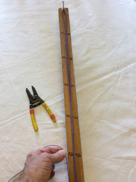
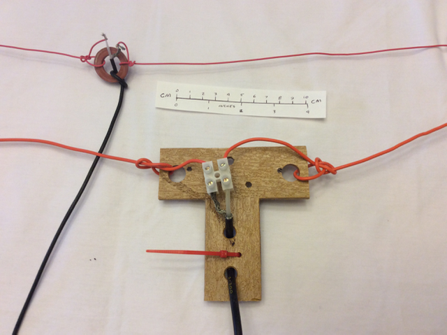
Step 1: cut the wires to length
This is easiest to do with a wire measuring board. I’m going to build the dipole for 14.1 MHz, and I think I will need 5.25m (17.25 feet) of wire for each side. But I’ll cut the wires to 5.5m each instead, to allow some length for adjustment. Determine the wire length for other bands here.
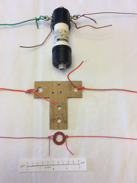
Step 2: attach the wires to the center insulator.
Don’t strip the insulation yet: the purpose is to transfer mechanical stress from the wire to the insulator. With light stranded wire, I just tie the wire to the insulator, which should provide a hole or ring for this purpose. With heavier wire, twisting it around itself a few times may be adequate. Leave enough extra on the end to reach the electrical connection point with some slack.
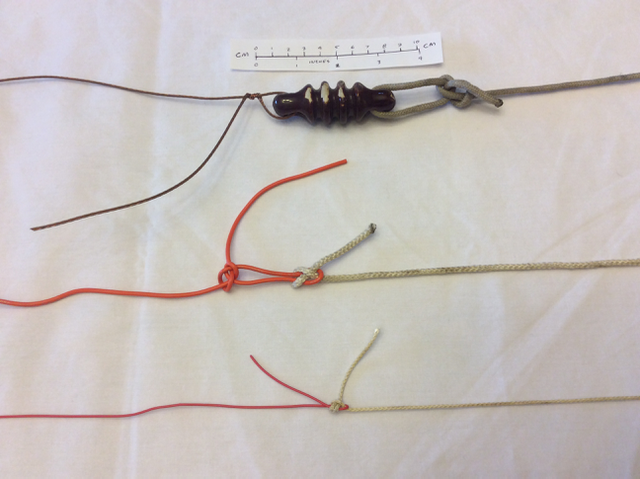
Step 3: attach the insulators and ropes on the ends of the wires.
For light wire, tie it in a knot. For heavier wire, wrap it around itself.
Note that I intentionally made the wire a bit long so I could trim it to length. If I tie the insulator at the very end of the wire, I have to untie it to make adjustments. Instead, I leave some extra wire hanging down at the end that can be trimmed or folded back for adjustment without needing to untie the support ropes (if I can reach it from the ground).
With synthetic rope and power levels up to 100 watts or so, the rope usually makes an adequate insulator all by itself.
Step 4: attach the coax to the center insulator.
If the center insulator has a coax connector, this is pretty simple, though you might want to add some additional strain relief to the coax. Otherwise, the coax can be secured by passing it through holes in the insulator, or by using tie wraps, etc. Leave enough free coax on the end to make the electrical connections.
When you have completed this step you should be able to pull on the wires and/or the coax and not have anything move or shift.
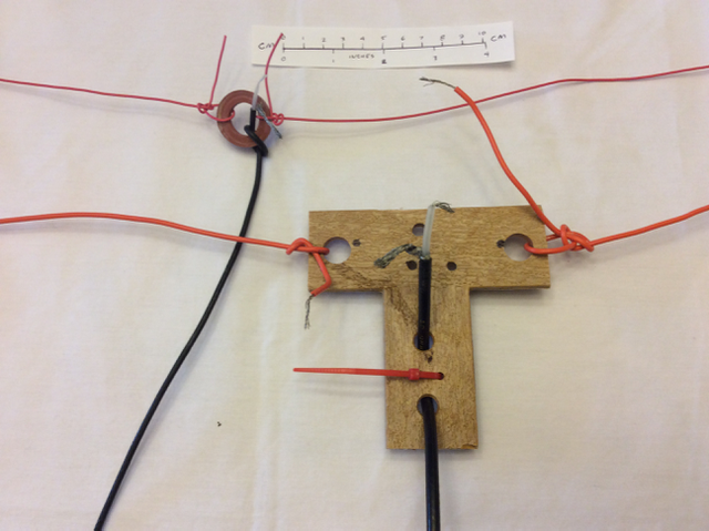
Step 5: connect the wires to the coax.
One wire goes to each side of the coax (or the balun). You will need to strip the ends of the wires if they are insulated. In some cases you might need to crimp a lug on the end of the wire, while other cases may require soldering.
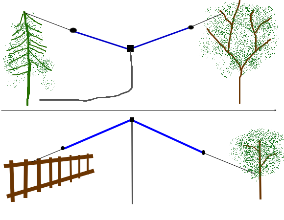
Step 6: put up the antenna and adjust the length for your desired frequency.
String it up the way you plan to use it: here are two common options:
Check the SWR across the band. If the minimum SWR point is too low in the band, the ends need to be shortened (cut off or folded back). If it is too high in frequency, it needs more wire added on the ends (this is more difficult than cutting it, which is why I start with the wire a little bit too long). The Wire Length Table will give you an idea of how much to trim or add.
Note: if you are measuring SWR using a radio with a built-in tuner, disable the tuner while making these measurements.
Once you get the antenna adjusted to cover your desired portion of the band, you are done. Congratulations! Well, almost…
Step 6: weatherproof the connections.
Getting rain in your coax cable is not a good idea – it will greatly increase the losses, and all you can do is throw it away and replace it. So if your antenna is likely to get wet, make sure that all exposed parts of the coax and electrical connections are covered with some sort of sealant. But often it is a good idea to try out the antenna and make sure it is working first before you coat it in gunk.