Half-Wave Dipole Length
last updated 4 December 2023.
The “traditional” formula for the length of a half wave dipole is 143 / F in meters (or 468 / F in feet), where F is the frequency in MHz. However, this is only a rough estimate, and doesn’t consider several other factors.
We can get a sense of the variation by modeling a dipole that is 20 m (65.6 ft) long. By the metric equation, this should be resonant at 7.15 MHz. (The Imperial formula gives 7.132 MHz instead.)
height above ground
Two important parameters are the wire diameter and the height above ground. Here is a chart of the modeled resonant frequency for 3 wire diameters, for a variety of heights above ground in 2 m (6 ft) increments:

The first thing we notice is that the resonant frequency varies with both the wire size and the height above ground, and is not a nice linear function in either case.
Another important result is that the modeled resonant frequency is always higher than the calculated result. This means that using the traditional formula risks cutting your antenna too short.
ground characteristics
We can also look at different ground types: in this case, “average”, “very good”, and “poor”:

In this case, the “very good” ground comes close to the traditional metric formula at 0.15 to 0.2 wavelengths above the ground. However, at heights just below 1 wavelength, the error is higher than for other ground types.
inverted vee elements
There are several online calculators that give a slightly different formula for an inverted vee as well: and they don’t all agree on what that formula should be. Let’s look at why there is some confusion:

This plot shows the resonant frequency vs. height in meters for the center of a straight dipole (green), a 120 degree (60 on each side) inverted vee (yellow), and a 90 degree (45 on each side) inverted vee (orange), all with the same overall wire length of 20 m (65.6 ft). Normally, we expect bent antennas to resonate slightly higher in frequency than straight antennas. In this case, that is generally true, except at very low heights. (The lines for the inverted vees are truncated at low heights where the ends of the elements would intersect the ground.) This due to the capacitance between the wire ends and the ground, which lowers the frequency at low heights, but has less effect when the antenna is higher.
There are several other factors, however, that are more difficult to model.
wire insulation
The type and thickness of the insulation on a wire also makes a difference. Enameled magnet wire can be considered bare for practical purposes, but a plastic insulation such as polyethylene, PVC, or PTFE will have a measurable effect. One problem is that many types of insulated wire don’t provide details on the characteristics of the plastic used, and the chemistry may change over time. A traditional estimate is that insulated wire lowers the resonant frequency of a dipole by about 3%.
attaching wire to insulators
This actually can make a significant difference, and it varies with whether the wire is bare or insulated.
When a bare wire is folded back on itself through the hole in an insulator and twisted, the wires make electrical contact, and the effect is as if the end of the wire is slightly fatter, increasing the capacitance.
However, when insulated wire is folded back on itself and twisted or tied in a knot, there is no electrical contact between the two sides, and the full length of wire is still active. But due to the coupling between the two wires, it isn’t the same as if the same wire were straight, either. My practical rule of thumb is that folding back the end of an insulated wire shortens the electrical length by about half of the amount folded back. So, if you have a half wave dipole, folding back 1 m (3 ft) of wire would be equivalent to cutting off 0.5 m (1.5 ft) of wire. This means that, with insulated wire, if you tune your dipole by folding back the wire, do not cut off the folded portion, or the antenna will be too short!
The same applies to tying knots in the wire. I generally tie a loop knot near the end of a wire to attach the support rope, leaving a “tail” of wire hanging down to cut back for tuning. The wire in the loop knot acts more like an inductive shorted stub rather than part of the radiator. In one case, I ran out of tuning “tail” with the antenna still too long. I untied the loop and retied it a little further up the wire, and now the antenna was too short, even though it used exactly the same wire as before. (I ended up adjusting the antenna by finding the right spot to tie the loop.)
other parallel elements
Using multiple dipoles for different bands on a common feedpoint can make a simple and effective multiband antenna, but, especially when the bands are close together (like 20m + 17m + 15m + 12m + 10m) the tuning of some elements will affect the resonant frequencies of others. The usual approach is to start tuning with the lowest frequency element and work up, as the longer wires are less affected by the shorter ones. The closer the wires are to each other physically, the more the interaction among them: using multi conductor ribbon cable for parallel dipoles almost always requires repeated adjustment to get them to work. In one case, adding a dipole for 60m to an antenna with 40m and 80m elements shifted the 40m resonance up about 200 kHz, but the 80m resonance was unaffected.
baluns
An imperfect balun, or lack of a balun, can also shift the resonant frequency of an antenna. For example, a 1 : 1 balun wound with wire rather than 50 ohm coax will transform the impedance slightly due to the mismatch on the wire. Air core chokes and voltage baluns often have shunt reactance that can change the tuning. Without a balun, the coax shield becomes part of the antenna in parallel with the wire on one side, and can not only change the resonant frequency, but may even cause additional resonances due to the coax length.
is there a better formula?
Not really. At least, not one that is easy to calculate by hand.
The problem isn’t that the constant in the “traditional” equation uses the wrong constant, but that the resonant length simply doesn’t follow any such a simple formula as closely as many hams expect it to.
So we have to change our expectations. I generally use the formula (or an approximate value from experience), then add some extra length to it, and plan to trim the antenna to the desired resonant frequency as needed. Once I get it tuned in a typical installation, it usually will work well enough each time it gets set up, even if the resonant frequency shifts somewhat.
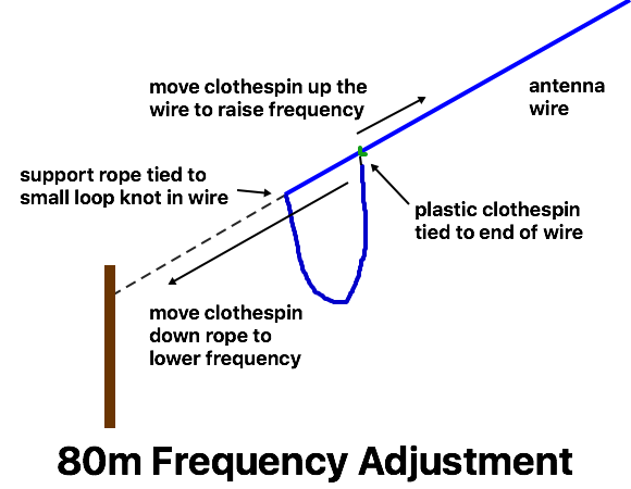
If it need to be able to fine-tune a portable antenna for minimum SWR in the field, then I use something like the tuning method for the dual-band dipole, by moving a clothespin along the wire (or support rope) to adjust the frequency.
I wasn’t entirely happy with these results, as they didn’t seem specific enough for many builders. After taking a lot of measurements, I have added a Dipole Length Table with expected wire lengths. This is based on the total length of wire used (so how long to cut the wire off the spool) rather than the overall antenna length. I’m not done with my experiments yet, but at least it should provide some useful guidance.
BACK TO:
RELATED LINKS:
Field Day antenna selection guide
antenna construction and supports
simple construction of wire antennas
winding rope and wire so they don’t tangle
EXTERNAL LINKS
W4RNL: a note on wire size and material
W4RNL: blunting the edge of cutting formulas
OWEN DUFFY: antenna loss in conductor materials