Dual-band dipole elements
Some years ago I was experimenting with a dipole kit for NVIS operation on 40, 80, and 160m. Many hams don’t have room for a full 160m dipole, so I started designing coil-loaded antennas, and discovered it was relatively easy to make a single element work on both 40m and 160m, with a length roughly that of an 80m dipole. That makes a very convenient tri-band arrangement, as the elements are all about the same length, and can be used to guy the supporting mast.
Since then I have made versions for 80m + 20m, and for 40m + 10m, using just a single loading coil in each wire rather than a trap. This works best when the ratio of the two frequencies is about 4 : 1 (probably usable between about 3.5 : 1 and 5 : 1).
The 80m + 20m version makes a great Field Day antenna when combined with a 40m element, although the bandwidth on 80m is rather narrow. The 40m + 10m antenna was designed to fit in an attic, and 10m operation was a nice bonus. Any of these elements can be used with the Portable Dipole Kit.
The concept is pretty simple: it is a standard coil-loaded dipole on the lower frequency, and the coil is large enough to act as a trap on the higher frequency (but best to operate it below self-resonance). For a half-length dipole on the lower band, the coils need to have about 1200 ohms of reactance, but the exact value isn’t critical, as the end wire length can be adjusted to accommodate a range of coil sizes (or the coil adjusted for the desired antenna length) to set the low frequency resonance.
Design
Now, usually I would wind such a coil as a separate unit, then attach the antenna wires to it. This makes it easier to adjust the coil for proper performance. But I was curious to see if I could make this work without needing to adjust the coil: that would permit each half of the antenna to be built using a single piece of wire for the antenna and the loading coil, with adjustments only at either end of the element. To do that, the exact inductance of the coil can’t be critical, because there always is going to be some variation in how it is wound.
And, sure enough, it works. However, there are a couple other factors that need to be considered…
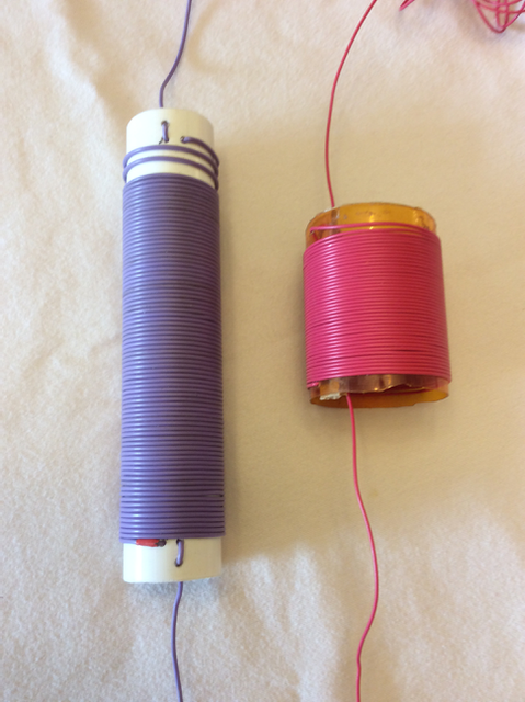
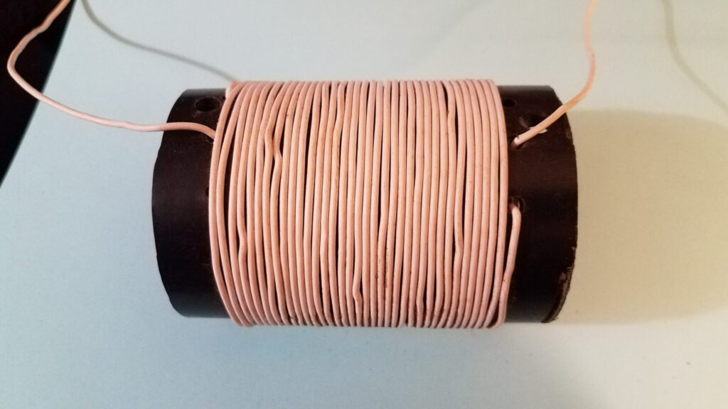
The first is the coil former. I don’t assume that you have access to the same sizes that I used. One set was wound on plastic pill bottles about 50 mm (2 inches) in diameter. Others were wound on plastic water pipe of 33 mm ( 1.3 inches ) to 60 mm ( 2.4 inches ). The length required depends on the turns spacing, which is a factor of the wire (and insulation) thickness and spacing between turns. I found the coil calculator at hamwaves.com to be invaluable for this purpose: not only is it more accurate than others, but it calculates the length of wire required and the resonant frequency of the coil in addition to the inductance. I set the wire size to the actual conductor diameter, then made sure that the winding pitch was big enough to account for the insulation on the wire. That allows for a lot of variation in wire size, insulation thickness, coil form dimensions, etc. You want to make sure that the self-resonant frequency of the coil is higher than the upper frequency of your antenna. For the 80m + 20m version, my target inductance was 50 uH. You can use the K7MEM’s Loaded Dipole Calculator to calculate the required value for other bands by entering the appropriate wire lengths. If you are using wire larger than about 1 mm (AWG #18), it may be best to use a different wire to wind the coils rather than trying to build the whole antenna with one continuous length. At least I had difficulty designing a suitable coil with a high enough self-resonant frequency with larger wire, even varying both the coil diameter and length. You might do better.
I chose plastic pipe with the thinnest walls that I could get, to minimize the plastic inside the coil. If the material is lossy, then it may get hot and deform. Theoretically it is best to leave some space between the turns to reduce the self-capacitance (which also reduces dielectric losses in the wire insulation), but that isn’t always convenient when you are trying to reduce the weight of the wire and the coil form.
With the 50 mm (2 inch) plastic medicine bottles, I used 40 turns of 0.4 mm (AWG #26) insulated wire, and the whole antenna element (both sides) is just under 200 g (about 6 oz.). The 33 mm (nominal 1 inch PVC pipe) used 80 turns of 0.6 mm (AWG #22) wire 140mm (5.5 inches) long, and weighs 320 grams (10 ounces). The version we built for use in an attic used a cardboard tube, because it would be protected from the weather.
The other issue is the bandwidth: a coil-loaded dipole has a narrower bandwidth than a full-sized dipole, and it was already difficult to cover both SSB and digital on 80m with a single antenna. For portable use, where it may get set up differently each time it is used, we need to provide for field adjustment if needed, even if it is only used for one mode. But there is a convenient way to handle that as well, allowing it to be tuned anywhere across the 80/75m band from 3.5 to 4.0 MHz as desired.
Construction
Now, to build it. For simplicity, we are going to waste some wire. For the 80m + 20m version, I started with 5.5 m ( 18 feet ) of wire on each end of the coil, plus the length required to wind the coil. (This will vary with the size of the former and the wire thickness.) Drill a couple holes at each end of your coil form with the desired spacing. Pass the first 5.5 m ( 18 feet ) of wire through one hole, starting from the outside of the coil form. Then pass it back out through the second hole in the same end. This provides some strain relief.
To make things much easier: roll up that 5.5 m of wire and stuff it inside the former while you are winding the coil.
Next, wind the required number of turns, or the calculated length of wire in the coil, around the former, then pass the end through a hole in the other end. The remaining end should be about 5.5 m ( 18 feet ) long! Again, pass the wire through a second hole for strain relief.
That should give you a coil with equal amounts of wire sticking out each end. Or close enough. If it doesn’t seem right, unwind it and do it over. Then make a second one. All that is left is to tune it up.
Tuning the antenna

One end of each assembly attaches to your dipole center insulator, and the other ties off with a rope to your fence or other end support. You could end up trimming 30 cm (1 ft) or more off the inner end (at the center insulator), so give yourself some extra wire length between where it ties and the electrical connection to make it easier to trim. (And if you use lugs on the ends of the wires, don’t crimp it on until you finish tuning.)
My dipole initially was resonant at 13.5 MHz. Trim the ends of the wire tied to the center insulator to put the 20m resonance where you want it in the band. I had to remove 30 cm (1 ft) to reach 14.05 MHz. It should be wide enough to cover digital/CW and SSB. Once that is adjusted, check the 80m resonance: it probably will be below the bottom of the band. I think mine was around 3.200 MHz. Gently trim the end back until the resonance is just below the band, about 3.450 MHz. I had to remove about 1 m (3 ft), but this will depend on the details of the coil.
Now, measure in about 1.5 m (5 feet) from the ends and tie a small loop in the wire. Attach your tie-off rope to this loop, so the end of the wire hangs down. This is how we make it field tunable. You need a couple of plastic or wood clothes pins, alligator clips, or similar. Attach them to the end of the wire with a short piece of string or fishing line. (You don’t need an electrical connection.)
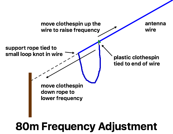
Stretch the end of the wire as far down the support rope as it will go, and clip onto the rope to hold the wire in place. This is the lowest frequency – it should be just a bit below the band to allow for some field variation. As you move the clip higher up the support rope, more of the wire is folded back, raising the resonant frequency. But the frequency shift isn’t linear. If you clip the clothespin as far up the wire towards the loading coil as it will go, that should be the highest frequency. Make sure it covers up to your maximum desired frequency, or a bit higher. If it doesn’t go high enough, untie your loop and move it higher up the wire. In the end, you should be able to adjust the resonant frequency anywhere in the band simply by moving the clips up and down the wire / rope. If you want to get fancy, you an mark these points, perhaps every 100 kHz or so. (They will change slightly when the antenna is installed differently, but that will give you a good starting point.)
And… there you go! Try it out and make contacts.
The SWR might not be as low as you might wish on 80m, since the shorter antenna will have an impedance below 50 ohms, but it should be better than 2 : 1 or so. If the SWR is too high at the dip, you can add a shunt coil across the feed point to correct it.
This combined with a 40m wire dipole makes a great portable setup, giving local NVIS and longer distance coverage with the same antenna. The 40m + 160m version along with an 80m dipole gives 3 popular NVIS bands on a common feedpoint, making it easy to change operating frequency as conditions require.