Portable Dipole Kit
last updated 18 February 2026.
This is a larger version of my original backpack dipole kit. I now use it for all sorts of temporary antennas. It has simplified not only portable operation, but also experimenting with various antennas, and can be adapted to many different purposes.
There is nothing particularly special about it: it is just a dipole center insulator attached to a length of coax, with wires for various bands that can be added in any desired combination. Adding another band is simply a matter of measuring two more wires (which is easy to do with a wire measuring board). The hardest part for me is deciding which spool of wire to use.
Video:
So let’s first look at my requirements:
- A single convenient package that can cover all HF ham bands. (It can be extended to cover 160m, 6m, 4m, and non-ham frequencies as well.)
- Can be installed in different configurations: I can put it up for just one band or several as desired, without it needing to be larger than necessary. I’ve also used it for wire verticals and loops.
- Easy to install and use. I can loan it to someone with minimal instruction.
- No antenna tuner needed.
- Supports NVIS propagation. (This eliminated most vertical antenna options.)
- Cheap, simple, easy to build.
- Capable of multiband operation without readjusting the antenna when I change bands. (This is very handy at night or in bad weather, and eliminated some options such as a linked dipole or a reel dipole.)
The basic idea is trivially simple, but I’ve made some refinements over the last 40+ years to make it easier to use. Let’s look at each of the components individually.
Coax cable
My original kits had about 10m (30 feet) of RG-58 ( 5mm ) coax cable. That’s a typical maximum height for a lot of portable antennas. I’ve built more recent ones with 15 – 20m (50-60 feet) of cable, as our Field Day antennas tend to be closer to that height. These lengths are sufficient for a lot of portable operation, and they allow the cable to reach the ground in many cases. If a longer cable is needed, a length of heavier coax can be run along the ground to the station. That keeps the weight on the antenna at a minimum, while allowing lower loss feedline for longer runs.
But there is nothing critical here: you can use other types of coax or other lengths to meet your needs. I use RG-174 (2.5mm) for my backpack kit, and some RG-8x in another kit. If you are using 75 ohm coax, you might cut it to a half wavelength on 40m, so the impedance shift is minimal on 40, 20, 15 and 10m.
The coax is permanently secured to the center insulator, with a connector to match your equipment on the rig end. That helps to reduce weight, and permits robust strain relief on the coax at the center insulator.
Center Insulator
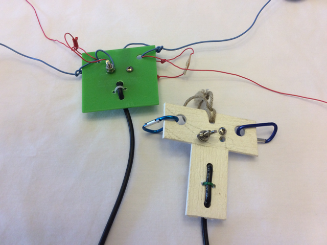
The center insulators have a number of features, as shown in the photos.
- Holes to tie the antenna wires to the insulator for strain relief. Larger holes are easier to work with. We are experimenting with using small clips or carabiners for this purpose as well, for the benefit of those who aren’t as familiar with tying knots. In that case, a small loop is tied once in the wire, or a short loop of rope is tied to the wire, that clips on to the insulator. (The clips do NOT provide electrical connection.)
- Coax strain relief. The simplest approach is to pass the coax through two holes in the flat insulator material and cinch down the coax with a cable tie between the two holes. Other methods are possible.
- Connections to the coax conductors. Generally I put a lug on the end of the coax and connect it to a bolt that passes through the insulator. One nut holds the bolt to the insulator, then two washers and a wing nut provide for connections to the wires. Stainless steel or brass hardware are preferred, but regular steel hardware should last many trips with care, and can be replaced if it starts to rust. Note that the bolts stick out on opposite sides of the insulator: not only does this help to prevent short circuits, but it keeps me from scraping my fingers on one bolt while tightening the other (obviously the voice of experience!). (A bit of glue, or beating the end of the bolt with a hammer once everything is assembled, will help to keep the wing nut from falling off and getting lost.)
- Loop for hanging. Generally I drill an hole in the top center and provide a short rope loop to hang the insulator by, but I’ve also managed by tying a rope though the holes for the wires.
- Weatherproofing. If it is going to be used out in the rain (which is likely here in Oregon) then I cover all exposed portions of the coax braid with some sort of waterproofing goop. My favorite is a spray-on sealant called “Flex-Seal”, but I have used hot melt glue, Liquid Electrical Tape, silicone sealant, Coax Seal, and child’s modeling clay.
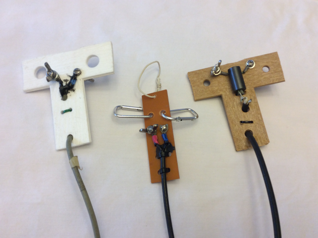
The insulator itself is some sort of plastic, with enough thickness that it won’t crack or tear. I like PVC because it is somewhat soft, and with a bit of smoothing of cut edges it doesn’t nick the wire insulation. Plastic kitchen cutting boards are a common material. You will see a lot of “T”-shaped insulators in my photos: there is no magic in this shape, although it works well: it happens to be the easiest way to cut insulators from scraps of PVC outdoor “privacy lattice”, of which I have a lifetime supply. One advantage of this material is that it is designed for outdoor use, and doesn’t degrade in sunlight as many other plastics do. Generally that isn’t a problem for temporary antennas, but some of my “temporary” antennas stay up longer than my “permanent” ones. My backpack kit uses a slice of rubber radiator hose for the center insulator.
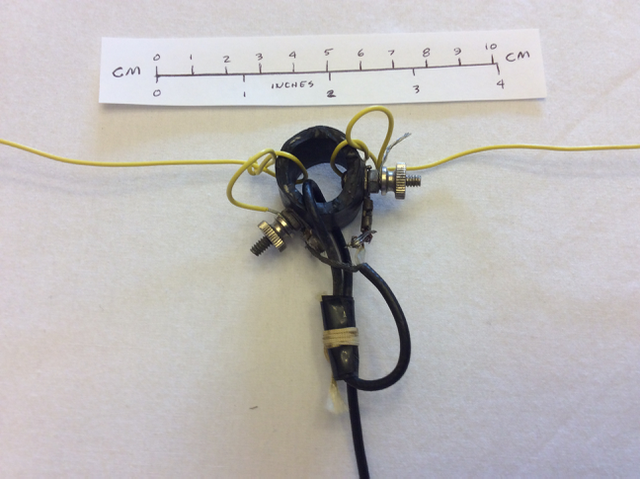
Balun. Or not.
Most of my dipole kits don’t include a balun, as it adds extra weight to the antenna. And most of the time this isn’t a problem with simple portable antennas. But sometimes I notice my mic is hot with RF, or I get two SWR dips across the 80m band when I am only expecting one. Those are symptoms of common mode current due to lack of a balun (along with increased pickup of local noise in the shack). So I now have one prototype center insulator that includes a balun, made from winding a twisted pair of wires through two ferrite cores, one on either side of the center insulator. The twisted pair was quicker to wire up than using RG-174 or RG-178 cable. The short 30cm (1 foot) length of feedline with unknown impedance causes a bit of a shift in the resonant frequency of my wire elements, but the normal tuning process corrects for that.
You can see the right-hand insulator in Figure #2 includes a balun made using 2 type #31 ferrite cores, one on each side of the insulator. I’ve changed the winding from a twisted pair to four turns of RG-178 (50 ohm) coax, because I was taking a lot of dipole measurements and wanted consistent results. One of my other kits has given me odd results on 80m, because the coax is resonant on that band. An extra turn would help on 80m, but I didn’t have room for it through the core. I also have a lighter weight set for backpacking that uses ferrite cores half that length – it is marginal on 80m, but mostly I use it for 40m and higher frequencies.
Does the balun make a difference? Often, I can’t discern any difference in operation. But occasionally I do run into quirks on bands where the coax is close to resonance, or the SWR curve of an antenna will change if I use a different length of coax.
Wires.
I tend to use mostly 1 mm (AWG #18) to 0.4 mm (AWG #26) stranded, insulated hookup wire for my portable antennas. I can tie knots in it like rope, and wind it up into small bundles. Solid wire tends to kink more, and takes more care to keep it from breaking. In the small wire sizes, the insulation adds strength to the wire. The insulation adds some uncertainty to the resonant length, but not enough to be a problem with simple dipoles. I’ve also used stranded stainless steel wire, and solid aluminum electric fence wire. Use what you have available.
I carry a set of dipole wires for each band I might want to use (each in a separate marked bag), and make a decision of what bands to add each time I set it up. If I know that I’m always going to want just 40m and 20m, for example, then I may leave them attached to the center insulator to reduce setup time. Where possible, I recommend color-coding the wires for each band. That makes it easier to avoid mistakes like connecting a 40m wire on one side and an 80m wire on the other, and wondering why it doesn’t work. Colored tape or paint can also be used to mark the ends.
I have found that after tuning the wires initially for minimum SWR at the desired frequency in a band, they can be installed in various other configurations and still be used without a tuner. (Running the wire along a barbed wire fence, however, does not work well, even if it is the only available support.) 80m and 160m are possible exceptions to this, as they often are very close to the ground (in wavelengths) and are affected by the capacitance to earth.
The 5 “traditional” HF bands worked fairly well with separate wires for each band connected in parallel, but the addition of the 1979 WARC bands, and recently the addition of 60m, complicates matters because the spacing between adjacent bands is smaller, and there is more interaction. So, for example, with 80m, 60m, and 40m connected in parallel, I see a small shift in the 60m resonance and a larger shift on 40m, compared to the same wires used on their own. I don’t have a good resolution of this yet
Ropes
In most cases, ropes in the 1 mm to 3mm range ( 1/16 to 1/8 inch ) are adequate, although larger ropes can be used. Again, use what you have available. I typically keep a number of 5 m to 10m (15 to 30 foot) pieces of rope with the kit for tying off the ends of the dipoles, along with a few longer ones for hoisting the antenna and covering longer spans where needed. Or I just throw a spool of nylon Mason’s Twine into the kit, cut it to the lengths I need the first time I use it, and keep reusing those pieces.
I also use a lot of baling twine (for tying bales of hay). This comes in a 1 km (half mile) or longer spool and is made of twisted orange plastic that is quite resistant to sunlight. It doesn’t roll up as small as some of the other types, but it is relatively light weight. It does abrade over time when pulled through trees, but we always had a spool handy when I lived on the farm, and now I have a lot of pre-cut pieces in 15 m to 50m (50 to 150 foot) lengths.
End insulators
I don’t bother with them. If I have 10m (30 feet) of plastic rope tied to the end of a wire, what difference is another short piece of plastic going to make?
But if you are running more than 200 watts, and especially with shortened antennas, or if you are using natural fiber ropes, then you might want to consider them.
Container
With multiple pieces of wire and rope, it is convenient to have a container to carry it that you can close so things don’t fall out. I sewed cloth bags for some of my kits (in a bright color, so I don’t lose the bag), or use whatever else I can find: bags from rice or other foods, plastic buckets or tubs, an old T-shirt with the sleeves sewn closed, small backpacks or duffel bags, or an old pillow case.
Using the dipole kit
Usually I put up the dipoles as inverted vees. I attach the center insulator to a telescoping mast or a rope over a tree branch, and raise it so the insulator is about chest high. That’s a convenient height for attaching the desired wires to the insulator. (If you use my standard method for winding wires, you can do this initially without having to unwind the whole length.) Typically I would then unwind each wire in turn and stretch it out in the expected direction laying on the ground. For the shorter wires, make sure you add enough rope to the ends so you can reach it once the feedpoint is raised up in the air! Then raise the feedpoint to the desired height and tie off the far end of each wire to a convenient anchor point with a length of rope. Especially if you aren’t trying to get the antenna up high in the trees, or have a lot of clutter to work around, it can go pretty quickly.
Suitable tie-off points for the ropes are fence posts, trees, small bushes, rocks, stakes in the ground, or even clumps of grass if there is nothing else available. I like to the the ends off at least head high so the ropes don’t become a hazard (especially if walking around at night), but that isn’t always possible. In some cases I throw a rope over a tree branch to get the wires more horizontal, but the primary support is still the center insulator
Sometimes I string it between two trees in the “traditional” horizontal dipole fashion: then I put a rope over each tree, tie them to the ends of two of the wires from different sides of the feedpoint (not necessarily for the same band, as the situation requires), raise it up in the air (allowing some sag), and tie off the remaining wires as inverted vees. With just two or three bands, it may be possible to have a shorter dipole hanging below a longer one, although you might need an extra rope or weight to keep the wires from twisting together.
Other configurations
The basic kit can be used in other ways as well. For example, using one wire as a vertical, and the other for that band as a radial. (If you have wires for a band at half the frequency, like a 20m vertical and a 40m dipole wire, then connect both ends of the lower frequency wire together to the “ground” terminal and spread it out to make two radials with the ends connected.) If I know that I may want to use the ground plane configuration, I may add a third vertical wire (of a different color) to each bag, that is tuned to resonate at the desired frequency when using the two dipole wires as radials.
On occasion I have had tall trees for supports that are higher than the length of my feedline. In that case, I have used one of the dipole wires to hoist the feedpoint, so that band is more “L” shaped. It still works.
Loop antennas can be connected directly to the center insulator, especially shapes designed for a 50 ohm feed, or those used with a tuner. In one case, I used a 40m dipole wire as a full wave loop on 10m, with the addition of one clip lead to work SSB or two to work CW. I also used one of the kits for our portable 5-element 20m wire delta loop beam.
When used for emergency communications, there may be times when some other group needs an antenna for a different frequency. With a spool of extra wire (or possibly adding extensions to, or folding back, the existing elements), this can be used on other HF frequencies. Or, of course, you can attach the elements for a reel dipole that can be adjusted for any HF frequency.
I now have several of these kits, and others have built them as well. Once I have cut and tuned the wires, it is easy to set up an antenna for any HF band quickly. They are also handy for testing various antennas, such as the dual-band dipole.
If you usually use a particular combination of bands, you can just leave the wires connected to the center insulator, while still having the option to reconfigure it in the field as needed.