Wideband 80m Dipole
In IARU Region 2, the 80m band extends from 3.5 MHz to 4 MHz. Building a dipole that covers more than about 200 kHz of the band with a low SWR requires some different techniques than we might use on other bands.
This antenna covers the whole range at less than 1.5 : 1 SWR (depending on the height above ground). And the frequency coverage can be tuned somewhat to center it in the band.
Like so many of my antennas, this is just an experimental prototype. I built it over 30 years ago, and we still use it occasionally, but the materials are not designed for long-term exposure to the sun. You might want to build it somewhat differently for a permanent installation. Also, the instructions probably won’t turn out exactly like mine: these are the “as measured” dimensions of one side of the antenna: I didn’t unwind all of it to see if the opposite side was the same, although I expect it is somewhat close. Over the years it has been adjusted in different ways, and one year at Field Day a “helpful person” cut several of the wires in the process of taking it down.
I don’t claim that this is an optimized version: there is plenty of room left for experimentation. But it meets the initial objective for low SWR across the band, and isn’t too difficult to build.
Theory
It is easy to think that one can cover the whole band by using multiple dipoles of staggered lengths, perhaps cut at 100 kHz intervals, and fed off a common feedpoint. But this doesn’t work as well as one might wish. Two dipoles at right angles will often give adequate coverage of both ends of the band, with a higher SWR in the middle. (And might approach circular polarization in the middle of the band.) However, the coupling between the wires, especially at the ends, makes such an antenna act more like a single wire.
By spreading the ends of the wires apart, they begin to act more independently, giving a wider bandwidth.
Initial Implementation
I begin my design by using the standard formula to calculate the required lengths for the highest and lowest frequencies in the band. These were 35.5 m (117 ft) and 40.5 m (138 ft). (Later I discovered that this formula does not apply here!)
I used a length of 7-conductor flat ribbon cable. Normally, I’d need the maximum length of cable (40.5 m), but by staggering the cuts in the center of the cable, I could get by with 38 m instead. Like this:
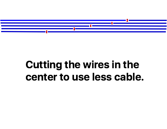
In this case, the ends of the original piece of cable connect to the center insulator, with the tapered length sections on the ends of the finished antenna.
Tuning
This is the point where I discovered that my simple approach didn’t work.
I strung up the antenna on my mast and checked the SWR using my radio. (This was before the days of antenna analyzers.) I couldn’t find any sign of resonance across the band, but right around 3.5 MHz I could see that the SWR was starting to drop. Apparently the antenna was resonant below the band, but I had no convenient way to measure just where.
The next problem was how to adjust the antenna: normally I would trim the end of the wire, but there were 7 wires on each end to trim in equal amounts. Because the end wires were thin, they were taped to the support rope, making it even more difficult. Finally I realized that the best place to trim the cable was at the feedpoint. So for each adjustment, I’d loosen the ropes, lower the antenna, disconnect the cable at the feedpoint, cut of some cable, strip the ends of all the individual wires, and reconnect them to the feedpoint. I don’t remember how long this took, but I appear to have shortened the antenna by 6 m (20 feet) by the time the resonance was within the range of my transmitter.
But the antenna still wasn’t working as I had hoped, and it was awkward to make adjustments. So I thought about how to reconfigure the antenna to make adjustments easier. That’s when I came up with the current version.
Construction
These instructions should get you close to my current antenna, without having to duplicate my initial mistakes. It probably could be optimized. I have another piece of ribbon cable in my junkbox, and some day I’ll try building another one. The dimensions are not particularly critical, given the wide bandwidth of the antenna.
Start with 30m (100 ft) of ribbon cable. Flat rotator cable probably is a better choice for sun exposure. Round multiconductor cable may work – I haven’t tried it. I used 7-conductor cable, but 4 or 5 conductors might be enough, and 10 conductors should be OK.
Measure in 12 m (40 ft) from each end and tie an overhand knot in the cable. This is where the support ropes will be tied.
Take the distance between the two knots and mark it into 4 equal lengths with small pieces of tape. You are going to make your staggered cuts in the center two of these segments. Carefully cut the edge conductor at the first tape mark from one end, and peel the single wire and insulation away from the rest of the cable. At this point, the spacing of your cuts will be determined by the number of conductors: with 5 conductors, the cuts would be at the first tape mark, halfway to the second, at the second tape mark (this will be the center conductor if there are an odd number of wires), halfway to the third, and at the third mark (the conductor on the opposite side from where you started). With 7 conductors, there will be two cuts in the middle of each of the two center segments, with the edge and center conductors cut on the tape marks as before. With an even number of conductors, there will not be a cut at the center tape mark. Lay out the marks carefully before you start, and make sure you don’t get the cable twisted so you cut the same wire twice!
Once you are done making the cuts, separate the individual wires in the staggered section all the way back to the knot. You should have 7 wire ends of different lengths (or however many conductors are in your cable).
This is the part that finally got the antenna to work. Sort the wires into two bundles: the even numbered wires in one and the odd numbered wires in the other. No, it doesn’t matter where you start the numbering, as long as adjacent wires go to different bundles. With 7 conductors, I had 3 wires in one bundle and 4 in the other. Use some short wraps of tape to hold the wires in each bundle together, especially near the end of each wire.
(Having just set it up again for testing, I strongly recommend tying two ropes to the knot at each end, and securing the various wire ends to those with heat shrink tubing to make the two sides. The individual wires are too weak to support the antenna otherwise. Also, leave a bit of slack in the wires, so that there isn’t any tension on them when the rope is pulled tight to support the antenna. Then I’ll tie a loop in the end of each of these ropes to attach the main support ropes.)
Installation
To install the antenna, tie your main support ropes to the knots in the cable. Each bundle then needs its own rope (which can be a lighter weight) that may need to be taped to the bundle of wires, as the single wire on the end might not be strong enough. The bundles then get pulled off at an angle to each other: the angle between them can be adjusted (by where the ropes are tied) to tune the antenna: spreading them apart raises the resonant frequency, and moving them closer together lowers it.
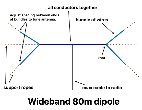
When the antenna is high in the air, we run one bundle along the main support ropes (tied to the knots) and let the rope for the other bundles hang down to the ground for adjustment by pulling it in different directions. If you need the two bundles at each end to be closer together (if the frequency is too high otherwise) then run the rope for the lower bundle through a loop or clip on the main support rope, possibly as a continuous halyard so you can pull on either side of the loop to raise or lower it.
Usually the antenna covers the band pretty well, but when installed in different positions we sometimes find that the SWR curve has shifted up or down by 100 – 200 kHz, and the field tuning corrects for that. If the tuning is too far off, then changing the cable lengths at the feedpoint is easier than at the ends of all the individual wires.
So, does it really work? I set up the original to check the SWR. This was with the antenna at a fairly low height over a parking lot, with no tuning. It isn’t quite as good as I had expected, probably due to the height above ground, but it certainly is usable, and with a bit of adjustment on the ends it should cover the whole band at under 1.7 : 1.

Ideas for further experiments: How few wires will work? Is there an optimum stagger for the lengths? Does it work with a bundle of individual wires? A round multiconductor cable?