MFJ-949 Antenna Tuner
last updated 2 January 2022
The MFJ-949 series tuners are some of the most popular ham designs. There have been several versions with minor changes: the one shown here is a 949C, and the current model is the 949E. This one had been well-used when I got it.
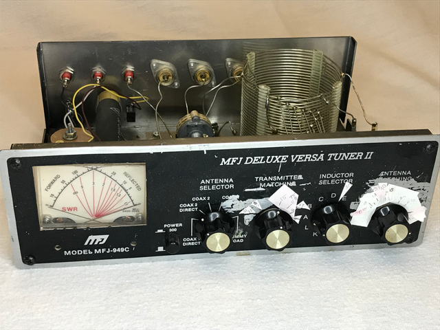
The bits of paper show where to set the knobs on different bands (for a particular antenna). I find this faster than trying to reset them to particular scale markings, especially since much of the right-hand scale has been scraped off. (Bits of self-stick notes work well, and can be color-coded for different bands.)
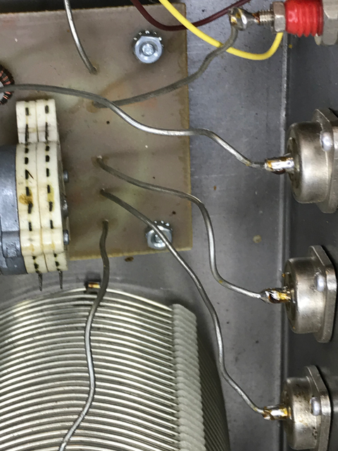
The tuner has 3 antenna positions, one of which has a single wire feed, or can be strapped to the built-in 4 : 1 voltage balun.
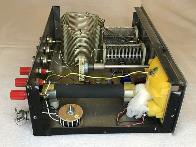
The two capacitors are 206 pF, and the upright coil 38 uH has 12 switched taps. The round device in the bottom left is the 4 : 1 voltage balun, the black tube above it is the dummy load resistor, and the white foam at the right end of the resistor is to hold the meter in place, which has come unglued.
I have not tried to measure the shorted-turn effect due to having the top and bottom of the metal case adjacent to the ends of the coil.
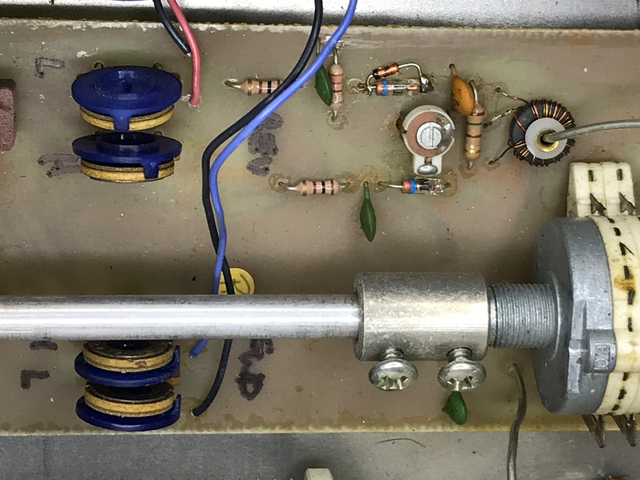
The tuner includes a cross-needle SWR / power meter, with 30 and 300 watt scales. Burned out diodes seem to be a common problem: because the board is difficult to remove, I just soldered the replacement across the original diode, as can be seen just above the white trimmer capacitor. The hand written markings for which knob adjusts each power reading is a good idea also, otherwise it is very easy to adjust the wrong one.
I also have a 949D model (in much nicer shape), which was very cheap at a hamfest because of extensive arcing inside. The capacitor shafts have to be insulated from ground, and apparently this one didn’t have shoulders on the insulated washers. The shaft had shifted sideways in the hole, and the resulting arc had burned away part of the original washer. A replacement washer with an appropriate shoulder to keep the shaft aligned in the hole fixed it up. I note that the advertising copy for the latest 949E model mentions heavy-duty shoulder washers, so this may have been a more common problem with some prior models.
The MFJ-949 actually did pretty well in my tuner efficiency test, sometimes better than the larger T-network tuners with roller inductors (but not always). The efficiency did drop somewhat on the higher frequencies, where the coil steps are larger than optimum. The way the tuner is wired, there is always 1 turn of the coil between the two capacitors, which generally would be connected directly together.
This is often the tuner I grab first, because it is smaller and lighter than many of the others, especially for a couple of transceivers that don’t include a built-in SWR meter. Now I would use an external 1 : 1 current balun in place of the internal 4 : 1 voltage balun, but often the stock configuration may work “well enough” if that isn’t practical.
Owen Duffy, VK2OMD, has several articles about calculating the efficiency of the MFJ-949 antenna tuner, and improving the heat dissipation to keep the coil supports from melting. Many of these are not necessarily specific to the MFJ-949, but it is used as an example because of its popularity:
Adjusting a T-match for best efficiency.
A look at internal losses in a typical ATU.