antenna tuner efficiency and ratings
last updated 28 February 2025.
When choosing an antenna tuner, hams often ask several simple questions:
- how high of an SWR can it match?
- how much power can it handle?
- what frequencies does it cover?
Unfortunately, these simple questions do not have simple answers when dealing with antenna tuners, even though some manufacturers are happy to provide answers that will encourage you to purchase their products, even if they are misleading or incomplete.
For an introduction, here is a beginner’s guide to antenna tuners
To better understand the practical issues, let’s explore an actual antenna to be matched and try several different tuners, to see what we learn in the process.
matching my doublet
I have a 40m doublet above the roof of my house, fed with about 17m (56 ft) of 300 ohm TV twinlead. I recently rearranged my HF station, and wanted to choose a good way to match it to my TS-450 transceiver.
Being in a hurry, of course, the quick approach was to hook the twinlead up through an external 1 : 1 balun and try matching it with the internal tuner in the TS-450. Wow! I was able to match it on every HF band except 60m (which the tuner wasn’t designed for).
Now, the tuner in the TS-450 is not like a lot of newer built-in tuners. It has a switched coil for each band, and a pair of motorized capacitors that spin to find a match. I have often been surprised by its matching range – it certainly isn’t limited to 3 : 1 SWR, even though the manual says it will match 20 – 150 ohms. (It just isn’t guaranteed that it can match impedances beyond that range.)
But I also knew that, when I’d tried the antenna before, several tuners had struggled to match it on some bands. This made me suspicious. So, rather than being in a hurry to get on the air, I decided to make some measurements. The first was to use an antenna analyzer to measure the actual impedance that the tuner needed to match: in this case, including the balun and the patch cable to the radio.
This is the result:
| frequency | load impedance | 50 ohm SWR (approximate) |
|---|---|---|
| 3.600 | 40 + j200 | 22 : 1 |
| 7.050 | 240 – j200 | 8 : 1 |
| 10.110 | 33 + j23 | 2 : 1 |
| 14.100 | 3 – j50 | 30 : 1 |
| 18.100 | 6 – j48 | 15 : 1 |
| 21.200 | 17 – j39 | 5 : 1 |
| 24.900 | 4 – j30 | 16 : 1 |
| 28.100 | 4 + j3 | 12 : 1 |
| 29.000 | 17 + j23 | 4 : 1 |
Here we see the first warning signs that this is not going to be easy: R values of impedance below 10 ohms.
Why? Because most tuners are less efficient at low impedances, unless they are specifically designed for it.
Let’s consider the 20m impedance of 3 – j50 ohms. Only the real part of impedance can dissipate power, so if we just look at the 3 ohms, then, at 100 W, we would need about 6 amps of RF, or about 4 times the current in a 50 ohm load. Because the power dissipated in a resistance increases with the square of the current, the same coil would dissipate 16 times the power (assuming we used the same amount of coil, which may not be the case).
Now, let’s go back to that reactance of – j50 ohms. While it doesn’t dissipate power, it does have voltage across it, and, with 4 times the current, the voltage will be 4 times as high as for a 50 ohm (resistive) load. So we have increases both the voltage and the current in the tuner by a factor of about 4, and the heat dissipated by 16, to match this specific impedance.
Let’s take a moment to state an important lesson here: tuners match impedance, not SWR. Yes, we normally see only the SWR value, and use that to adjust the tuner, but it is the actual value of impedance that determines the required tuner settings.
A classic example is the old Johnson AM transmitters from the 1950s and 1960s. They were specified to match impedances from 40 to 600 ohms. That meant that, using 50 ohm coax, they could match an SWR over 10 : 1 at high impedances, but couldn’t handle 1.5 : 1 at low impedances. While the actual matching range varied with frequency, it was often limited by the amount of capacitance required to match low impedances on 80m and 160m.
Another lesson is that many tuners are more efficient matching higher impedances than lower ones. The common “T” network tuner is a good example: it often is most efficient matching around 1000 ohms, while it can be very inefficient at 2.5 ohms, even though both have the same SWR of 20 : 1.
One other point to consider is the effect of the feedline. These are the impedances that I happened to get with my specific antenna and feedline length. If the twinlead had been 4.7m (15 feet) longer, or 3.8m (12 feet) shorter, the impedance could be over 10000 ohms on 20m instead, which would have resulted in a very different set of problems.
This is also a good example why a 4 : 1 balun is NOT necessarily a good choice between a balanced feedline and an unbalanced tuner. In this case, it would (theoretically) step the low impedances down by a further factor of 4, making them even more difficult to match efficiently.
meanwhile, back to the antenna…
So now the question still remained – was the internal tuner matching the antenna efficiently? There are ways to measure that, but I needed a simple approach that didn’t require me to construct test equipment. And really I just wanted a relative gauge of which tuners were better. So I designed an experiment.
Up in the attic I had an old 11m CB SWR and power meter with a nice big meter. Many power meters of that type were actually just an RF voltmeter across the feedline, which, of course, was only accurate when the SWR was 1 : 1. By putting this in line between the tuner and the balun, I could measure the relative output power from different tuners, because the impedance they were matching was constant on each band. I couldn’t determine the absolute efficiency, but I could see which tuners sent more RF down the feedline, hence were more efficient compared to the others.
Then I collected an assortment of antenna tuners from the garage:
- the internal automatic tuner in my TS-450
- Unique Wire Tuner
- Ten-Tec 227 (T network)
- MFJ 949C (T network with switched coil, one of the most popular types)
- MFJ 969 (larger T network with roller coil)
- homebrew white T network tuner, with roller coil (from a hamfest?)
- homebrew Ultimate Transmatch (that I built 50 years ago)
I’ve created separate pages to describe each tuner, along with comments on the efficiency tests and any specific features or quirks.
So here was my setup:

For testing the internal autotuner in the TS-450, I removed the external tuner and one jumper cable, so all were matching the same impedance on each band. The impedances that the tuners had to match weren’t exactly the same as what I had measured initially, due to the addition of the meter and one patch cable. (With an extra patch cable, the TS-450 wouldn’t match the antenna on 80m, so clearly it was at the edge of its matching range.)
My procedure for the external tuners was to set the rig to CW, turn the drive control to minimum, close the key, then increase the drive until I had enough RF to activate the internal SWR meter. That typically was 2 or 3 watts. I adjusted the tuners at that level until I got a good match, then increased the drive to 50 watts on the internal meter. At that point, I recorded the wattmeter indication. (A homebrew RF voltmeter used with a digital voltmeter would give better resolution.)
The meter readings weren’t anywhere close to accurate, of course, due to high SWR at that point. But they gave me relative readings, which I recorded for each tuner on each band, then used to plot the results in dB relative to the best tuner on each band. These have been fudged a little on duplicate readings so both marks show in the plot.
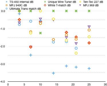
Measured loss in dB relative to the best tuner on each band. The horizontal scale is frequency, the vertical scale is relative output from the tuner for a fixed input power. These plots only apply to this specific antenna, and should just be considered approximate.
This doesn’t tell me the actual loss in each tuner, only how much worse it is than the best of the group. That means that the actual loss must be greater than the numbers shown here, we just don’t know by how much.
(Some tuners don’t have numbers for some bands, because they couldn’t get a good match. I also did not include figures for 10m, where my meter didn’t give good results.)
It may take some time to digest all this information, but a couple of things are pretty obvious:
First, the Unique Wire Tuner (the green Xs on the plot) almost always had the lowest losses of the group. For one thing, it is uses an “L” network, which theoretically will be the lowest loss configuration. But it also is configurable: I used 3 different arrangements of the components in matching this antenna, and two of them were the reverse of how it was designed to be used (due to the low impedances to be matched). Usually I was able to make a good guess what configuration to use based on the measured impedance, but swapping cables when changing bands is not particularly convenient.
Second, on 4 bands the autotuner in the TS-450 had at least 3 dB of loss beyond that of the best tuner, even though it was able to match the load with a low SWR. This means that, at full power, at least 50 watts is being dissipated in the tuner components (mostly in the coil). This is going to melt something with extended use, but there is no warning of this condition. Is it any wonder that tuners often fail, even when used within the specified power level?
Actually this is a fairly common problem with other types of tuners as well, especially the T network and derivitives (like the “Ultimate Transmatch”). There can be several different settings that give the same low SWR, but at different efficiencies. It doesn’t take a lot of dissipated heat to melt the plastic coil supports used in many inexpensive tuners.
Meanwhile, as we have seen above, the dissipation is a function of the impedance being matched. With a manual tuner (and older automatic ones) there is nothing to prevent it from being used to match an impedance where it may be only 50% efficient, or less. It may seem to work fine for casual SSB operation, but fail in a contest, or for some digital modes, where the duty cycle is higher so the heat has a chance to build up.
How do you specify the power rating for a tuner, when it depends on the impedance you are matching, how the tuner is adjusted by the operator, and how long you use it for? And, for a given antenna, how long the feedline is, because that affects the impedance. (If I had used a different length of feedline, so the impedance was 10000 ohms, then the voltage of the capacitors and other components may be the limiting factor.)
So when manufacturers rate their tuners for “300 watts”, or whatever value they may give, they are probably assuming a low duty cycle mode like casual SSB, and a “reasonable” load impedance, perhaps around 200 ohms. Don’t take that as an absolute guarantee, however. My “Ultimate Transmatch” tuner uses capacitors significantly larger than those used in most “300 watt” tuners, but it would still arc over at about 10 watts when trying to match an extreme load, like a 50 cm ( 18 inch ) clip lead on 80m, even though the tuner could achieve a match.
OK, we’ve learned that a tuner can overheat when matching a low impedance or other extreme load, even within the nominal rated power, and there is no warning. Well, there is a way to tell: after operating for a while, lift the lid and check the temperature of the coil with your finger. If it is too hot to touch, you clearly have a problem. Hopefully you can do this before it gets hot enough to melt anything. You don’t need to do this all the time, but at least once on each band when setting up a new antenna is a good idea.
QRP operators should note that, while damage due to overheated components is much less likely, they are still losing the same percentage of their power in the tuner, even if they can’t detect the heating. Small tuners designed for portable operation can be even worse, depending on the compromises to reduce size and weight.
T-network observations
Other than the Unique Wire Tuner, all of these use the common CLC “T” network, or a derivitive.

This allows matching a wide range of impedances with inexpensive components, without needing to reconfigure the circuit. The MFJ-949C and the Ten-Tec 227 used a switched coil, and the Ultimate Transmatch uses a length of coil stock with a clip that can tap it at each turn. The TS-450 autotuner uses a single switched coil for each band. The others use roller inductors, giving finer resolution on the setting. If we look at the results for these tuners, we don’t find a lot of correlation: no one tuner, or feature, is consistently better than any other, although the autotuner consistently has higher losses for loads under 20 ohms.
Generally, the setting for maximum efficiency with this circuit is to have maximum possible capacitance. This usually means having one capacitor set to maximum, and varying the other (along with the inductance) to get a match. But that isn’t always possible.
At lower frequencies, the capacitors may not be large enough, requiring more inductance than would be needed with larger capacitors. That increases the losses, particularly at low impedances. However, there is a practical minimum capacitance to physical capacitors, and large units that may give better efficiency at lower frequencies might not go low enough to match higher ones.
When the coil is not continuously variable, then the available increments of inductance may be too large to get a good match at any position. In that case, reducing the other capacitor can give a better match. This feature is one reason why this circuit is so popular with inexpensive tuners, but it also means that the tuner efficiency varies with the exact impedance to be matched vs. the available inductance steps, which varies among tuners. If you have a step where one capacitor can be left at maximum, it will be more efficient than using more inductance and offsetting the second capacitor to get a match.
This particularly became an issue on the higher frequency bands – in a couple cases the inductance was set to minimum, and it still wasn’t low enough to match, due to the inductance of the internal wiring in the tuner. Again, this is a trade-off in matching range: a large coil is needed to match low frequencies, while small increments are needed for higher ones. With the Ultimate Transmatch, I used just 2 turns (out of 60) on the coil to match on 20m, and shorted the coil on 10m, and it was still difficult to tune.
That actually provides another clue of tuner efficiency: when using a T-network tuner, if you can’t get a good match with one of the capacitors at maximum, check for heating in the coil.
Of course, that also means that you need to know which end of the scale is maximum capacitance. Some manufacturers think it makes sense to have “100” mean minimum and “0” mean maximum capacitance. I don’t. So I generally take the cover off and see. If the capacitor turns 360 degrees, then removing the knob and reinstalling it 180 degrees off will often fix the problem. Otherwise, at least make a mark or put a piece of tape on the tuner face to show where the setting is for maximum capacitance, as you should be using it often.
other observations
This is one of the few times I have used multiple tuners and compared them. Usually I just grab whatever tuner is handy. But using all these to match the antenna on multiple bands in the space of 24 hours gave me an opportunity to compare how easy they are to use.
I have to say that I was not impressed by the tuners that had roller inductors. True, they make it easier to get a precise match, but the process of finding a match is much slower. Part of that might be the physical condition of my specific tuners (many of which came to me after hard use). The MFJ-969 has a finger dimple to spin the dial for the roller inductor, but one finger does not generate enough torque to move it. I have to grab the knob with one hand and twist it, about half a turn at a time. (This may be due to damage or wear to the gear train.) The white tuner and the Unique Wire tuner both have cranks instead, and can be tuned faster, although I need a second hand on the tuner to keep it in place on the shelf as I tune it quickly.
Another aspect to consider is how easy it is to keep an eye on the SWR meter while adjusting the controls. Having to put my left hand on top of the MFJ-969 to hold it while turning the inductor with my right hand tended to make it hard to see the meters.
The easiest way to adjust the switched T-network tuners was to step through the inductance settings (or make a good guess to start), then set one capacitor to maximum and swing the other through its range. If there was no dip in the SWR, vary the other capacitor. If still no result, then try a different step. Once I found a dip, then I optimized all the settings as needed to get a low SWR, trying to keep the capacitors as fully meshed as possible.
I used the same approach with the roller inductors, but instead of proceeding to the next coil switch position, I cranked the coil a few turns and tried again.
When the load was such that I couldn’t leave both capacitors set to maximum, it was more difficult. In one case, I set both capacitors somewhere around mid-scale, and cranked the roller inductor from one end to the other. Not only are such settings less efficient, but, for the same reasons, they have a higher Q, so the tuning is more sharp. That can be an issue with large capacitors and small knobs, where the required angular resolution is pretty small on the higher bands.
My favorite for smooth tuning? The Unique Wire tuner. Yes, it is annoying to have to swap cables on the back to change the configuration. But once set up, it was pretty easy to find the dip, and there is only one setting that gives minimum SWR.
lessons learned
So what did we learn from this extended process?
While the internal autotuner in my TS-450 is capable of matching a wide range of impedances, it may not be very efficient with extreme loads. It’s probably worthwhile checking the SWR first, before engaging the autotuner, to get a sense of potential problems.
The same goes for many types of manual tuners, particularly for low impedances at lower frequencies.
Impedances with low values of resistance tend to have higher tuner losses.
With a common CLC T-network tuner, consider it a potential warning sign if you can’t get a low SWR with one capacitor set to maximum (which may not correspond to the largest number on the scale).
Using an RF voltmeter between the tuner and the antenna seems like a reasonable way to get relative readings of tuner efficiency, even if it doesn’t give absolute numbers, as long as the tuners are matching the same load impedance. This approach can be extended to balanced lines. I’ll probably use a digital voltmeter for the readout in the future.
does this apply to relay-switched autotuners?
At least partially. Many have SWR limits built into their digital control, so they can simply refuse to match a load outside a specified range. They can have a wider range of capacitance and inductance, in smaller steps, although it is possible that some designs have not been able to match particular loads because the required capacitance fell between the available steps.
The typical failure modes include the relay contacts arcing and sticking closed, which can cause the tuner to match some impedances and not others. This often manifests as it working on only some bands.
However, the issues with low resistances remain. And, due to the small size, they often use smaller components crammed in a small space, and are more prone to overheating, particularly at high duty cycles. It isn’t as easy to stick a finger on the coil to check the temperature, either.
so, which tuner am I going to use?
For the moment, probably the Unique Wire Tuner, and I’ll see if there is another configuration that does better on 30m.
But a better long term approach will be to find a combination of antenna and feedline lengths for a doublet that gives higher resistive values. Or I may see if I can fit a bow tie loop on my roof, which could improve performance on 80m. If I come up with a good solution that will become semi-permanent, I may set up my switched tuner to make band changing easier.
BACK TO:
RELATED LINKS: