A home-made “Ultimate Transmatch”
last updated 2 January 2022
QST magazine for July 1970 included an article by Lew McCoy, W1ICP, on a tuner circuit that he called the “Ultimate Transmatch”. The circuit looked like this:

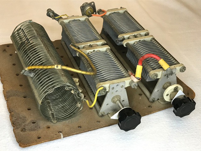
Shortly afterwards I was able to salvage a coil and some variable capacitors out of an old transmitter, so built my my first tuner using this circuit.

The capacitors are about 250 pF per section. The coil is about 60 uH, and is tied onto the bottom board with fishing line. The coil can be tapped on any turn, and is much larger than necessary. I rarely used more than 1/3 of it on 80m. (The original article called for 18 uH to cover 80m, and 28 uH for 160m.) I did add rubber feet on the bottom, so the mounting hardware didn’t arc to the transmitter case or whatever it was sitting on and I quickly learned to keep my hands away from the tuner when I was transmitting. It allowed me to match various end-fed wires, as well as coax lines. In fact, I could get a low SWR with a lot of different loads, including a 50 cm ( 18 inch ) clip lead on 80m. That is not to say that such a short wire was very efficient, of course, and the capacitors arced over at about 10 watts output, even though they are substantially larger than those used in commercial “300 Watt” tuners sold today.
But it allowed me to get on the air with a number of improvised antennas while I was in college.
Since then, I have learned a lot more about antennas, and we know a lot more about tuner efficiency. While this circuit can be tuned to a low SWR for many loads, that doesn’t mean that much power is actually being radiated. In one case, the coil wire was so hot at 50 watts that I burned my fingers on the wire (no, I wasn’t transmitting at the time).
If we look at the circuit, the only difference between this and the common T network is capacitor C1B. This capacitor is effectively in shunt with the coil, which increases the circulating currents (the primary cause of losses in such a tuner). The parallel combination of C1 and L increases the effective inductance, allowing a smaller coil, although losses are higher, especially for low impedances on the lower frequency bands.
At one point I read a commentary that W1ICP choose this circuit because the roller inductor he had on hand was a little too small to cover 160m in the standard T circuit.
Given that harmonic filtering shouldn’t be an issue with a modern transmitter, it is a better use of C1 to connect both sections in parallel and use a standard T network. This improves the efficiency. It is still possible to find combinations of settings where much of the power is dissipated in the tuner, but that can be minimized by trying to keep one capacitor set close to maximum at all times.
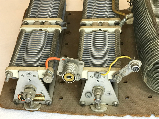
I keep thinking about converting this tuner to a conventional T network, but there is one problem, which we can see from the back of the tuner:

(Yes, that is an RCA audio connector for the tuner input.) The original circuit has one side of C1B grounded, and I used this to mount the input and output sockets. With the T network, there is no mechanical place to mount them. I’ll have to make a metal bracket for the ground connections that is insulated from the capacitors. That’s more trouble than it is worth at the moment. In the meantime I have a reminder of my early days, and an example that a tuner doesn’t need a fancy case to be functional. (But a cover of some sort to keep my finger off the circuit when I am transmitting isn’t a bad idea.)
After 50 years of knocking round without a protective case, the tuner is showing a bit of wear. The plastic coil supports have cracked at the ends impact, so one turn at each end of the coil is partly loose. The capacitor shafts could use some cleaning and lubrication to make them easier to turn, and larger knobs would be easier on the fingers.
While this worked well with my Heathkit HW-12 (3.8 – 4.0 MHz SSB only), when I used this in my tuner efficiency test it reminded that it didn’t do as well on the higher bands. On 20m, I used only 2 turns on the coil, and on 10m shorting the coil still resulted in higher inductance than necessarily, requiring that both capacitors be set to relatively small values, which were rather touchy given the large capacitance range available. It did rather well on 40m, but was towards the bottom of the list otherwise (and I couldn’t find a match on 30m, which had the lowest SWR). But, when that was all I had for an antenna tuner, I got it to work, and it probably would do better with higher impedance loads (and a smaller coil).