the Unique Wire Tuner
last updated 19 February 2023.
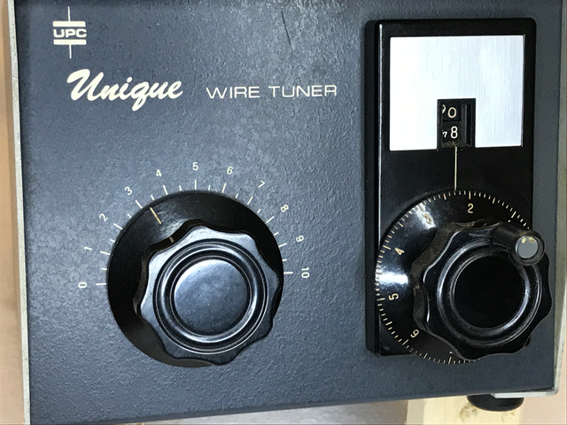
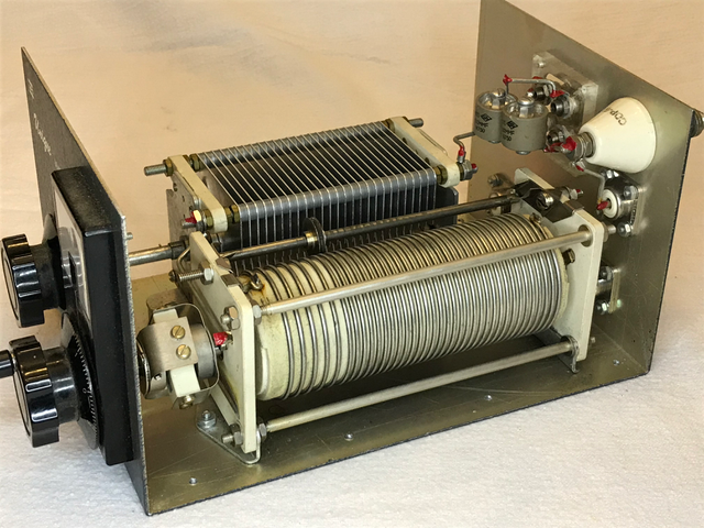
The Unique Wire Tuner was manufactured by the Unique Products Company. It is basically an L network, with a variable capacitor and a roller inductor, but the circuit is built so that they can be used in different ways.
As a conventional L network, the unit can be used with a series coil and shunt capacitor (“high-pass” configuration), or with a series capacitor and shunt coil (“low-pass”). There are 3 coax connectors on the rear panel: the “standard” output is connected to the junction of the two components, and has a ceramic insulated post for a single wire in parallel with the coax socket. The other coax connectors go to the remaining ends of the coil and capacitor: by shorting one of these to ground and using the other as the input, the tuner can be configured either way.
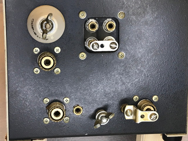
In the photo above, the single wire output terminal is in the upper left, with the output coax socket below it. Along the bottom are the input jacks, one of which is shorted to set the configuration. In the upper center is a shorting bar that can add series capacitance to operate as a T network.
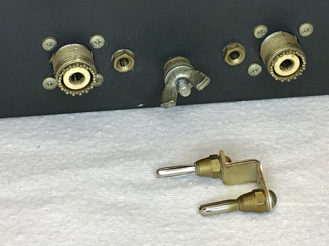
Each of these sockets has a grounded banana plug beside it. The shorting plug connects to that, along with the center pin of the coax socket to make a low-impedance ground connection. Then the other socket is use for input.
Does it matter circuit you use? Most modern transmitters should have sufficient harmonic filtering, so the “low-pass” configuration isn’t necessarily the best choice. Matching low impedances sometimes requires a shunt element with a small reactance. That can require an impractically large variable capacitor, but only a small inductor, which is much easier to build and takes less space. If you have problems getting a good match one way, try the other configuration.
The high-pass configuration will provide a DC path from antenna to ground through the coil to discharge electrostatic buildup on the antenna, as long a the extra capacitors aren’t inserted in the circuit.
The unit is intended to be used for impedances greater than 50 ohms, because the shunt element is across the load. It is possible to reverse the input and output ports to match low impedances. The traditional L network also has a limitation that, for impedances close to 50 ohms, the components required may be impractically large or small.
To get around that, and to avoid having to swap cables too much when changing bands, there is another feature that adds fixed capactors (50, 100, or 200 pF) in series with the output, making a T network tuner. This makes it possible to match impedances close to, and below, 50 ohms without needing to swap the input and output cables.
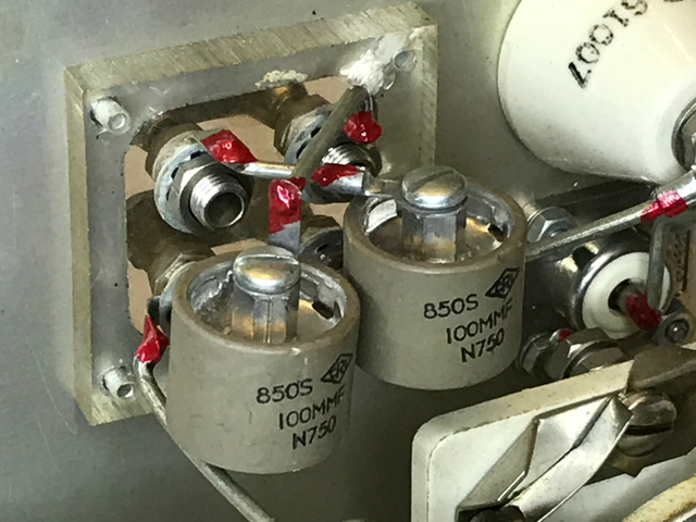
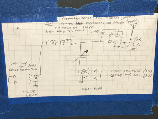
There are two 100 pF capacitors connected to 4 banana jacks on the back panel, with two jumpers provided. When one jumper is connected horizontally across the two bottom jacks, the capacitors are shorted, and the tuner functions as an L network. (The second shorting bar is generally installed in the upper jacks so it doesn’t get lost.)
Removing the bottom jumper and shorting just the upper pair of jacks, the two capacitors are in series, for 50 pF.
When either vertical pair of jacks is shorted, it adds one of the capacitors into the circuit, giving a choice of 100 (one jumper) or 200 pF (both jumpers vertical). Generally for best efficiency you would want to use the maximum capacitance that gives a good match.
And, in case the resistance is close to 50 ohms, but with some reactance, then the coil or capacitor (or both) can be used in series between input and output if the shorting bar across one coax jack is removed.
And that’s all there is to it: no metering or any other circuitry. Just a simple, rugged circuit. But it certainly is unique!
To keep track of everything, I taped a copy of the circuit to the bottom of the case:
How does it work? Actually, I haven’t used it much, because I’m often using antennas that don’t need a tuner, or transmitters that don’t include an SWR meter, and it is easier to use a tuner that includes one. It is a bit awkward if I have to switch configurations when changing bands, but generally, for wires over 3/8 wavelength or so, the standard setup works well, and it tunes easily. It should, of course, have some sort of ground system connected to the bolt on the rear of the case to load into an end-fed wire.
While it can be awkward to find the right configuration, and to swap the cables around when changing bands, I like this tuner. It was the best in the tuner efficiency test, achieving the highest efficiency on all bands except one. (And a different configuration might have worked better on that one.) I was able to guess which configuration to use in most cases, just knowing the load impedance, but trying to do so by experimentation is not easy. I ended up using 3 different configurations on different bands.
On the other hand, once configured, the tuner was the smoothest to adjust. In most cases, I could set the capacitor to maximum and run the coil through its range to find some sort of SWR dip, then adjust from there. If I didn’t see a dip, I’d set the capacitor to mid-scale and try again. (One could also make a reasonable guess of the coil setting based on the band, then run the capacitor through its range.) Both components have to be the correct value to get a good match, but there is no third adjustment to get confused with. This has been my experience with L-network tuners in general.
But I may try to adjust the antenna and/or feedline length so I don’t need to change configurations as often when changing bands!
Added note 19 February 2023:
Yesterday I found another “Unique Wire Tuner” with an identical front panel, but without the ability to change configuration, or the capacitors with jumper bars. It also doesn’t have the coax socket in parallel with the terminal for the antenna wire. It is just an L network with a shunt coil from antenna to ground, and a series capacitor from the antenna to the coax input (high-pass configuration).
I expect it will work about like the original for wires over about 3/8 wavelengths, where the impedance is over 100 ohms or so, but won’t be as flexible at lower impedances.
If you are shopping for such a tuner, make sure you get to look at the back of the tuner to tell the difference between them. The simpler version has only one coax socket, an insulated terminal for the antenna wire, and a ground lug on the back panel.