Analysis of Current Distribution on an Antenna
One of the most useful tools for analyzing antennas is being able to visualize the current distribution along the wires (or other conductors). This often gives a quick first-order indication of the resulting polarization and general pattern: not as quick as modeling software, perhaps, but something that most hams can do in their heads just looking at an antenna design, once they know how to do it.
The current distribution along an antenna determines the radiation pattern. When net current flow is mostly in one general direction, that direction corresponds to the antenna polarization. When currents flow one way on one part of an antenna and in the opposite direction on another part, they cancel each other with regard to radiation towards the viewer (assuming they are in the same plane).
This approach works best for planar antennas where the elements are connected together, such as loops or various types of curtain arrays.
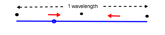
For example, here is a drawing of the current on a full wave loop antenna, including red arrows indicating the (nominal) direction/phase of the currents in the wire:
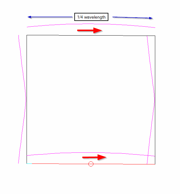
The current is maximum in the centers of the two horizontal wires, and minimum in the center of the two vertical wires. This was generated by EZNEC software, but can easily be done by hand. The red arrows show the relative direction of the standing wave current at a particular point in the AC waveform: it doesn’t matter which way they point, but the fact that both arrows point in the same direction (towards the right) indicates that the currents are in phase as viewed from the reader’s point of view, and the antenna is horizontally polarized. That means that there is a major lobe broadside to the loop, that is, in the direction of the reader.
Here are the basic rules that I have used to analyze the current distribution on antennas, even before antenna modeling software was available:
- The unconnected end of a wire is always a point of minimum current. I mark these with a dot.
- In a closed loop, current is maximum at the point opposite the feedpoint. I mark this with an arrow parallel to the element. It doesn’t matter which way the first one points.
- Points of maximum and minimum current alternate every 1/4 wavelength along the wire, until you reach the feedpoint.
- The direction of the current relative to the wire reverses in adjacent segments. On a straight wire, this mean the currents are out of phase. If the wire is bend around (as in the full wave shown above), then they can be in phase.
- The phase of the current is the same on both sides of the feedpoint. But you might need to go to the other end of the wire, mark the minimum voltage points back towards the feedpoint, then add in the phase for the maximum current points.
- An antenna fed at an arrow will have a low feedpoint impedance (typically less than 600 ohms). An antenna fed at a black dot will have a high feedpoint impedance (typically over 1000 ohms).
We can then look at the directions and locations of the arrows and make some observations about the resulting antenna behavior.
Let’s start with a simple half wave dipole as an example:
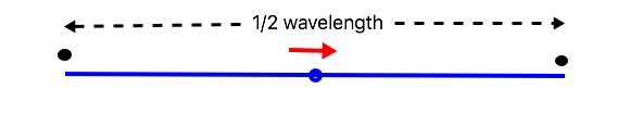
We start by placing a black dot at each end, because the wires are not connected to anything else. (Of course, you are welcome to use whatever symbols you prefer.) Then, starting from either end, we measure back 1/4 wavelength and place the red arrow pointing in either direction along the wire. That happens to be the feedpoint, so we go work back from the other end… which comes to the same red arrow at the feedpoint. Because the phase is the same on each side of the feedpoint, we already know the arrow is pointing in the correct direction. Because there is an arrow at the feedpoint, we know that it is a comparatively low impedance feed.
Now let’s see what happens with a full wave dipole:
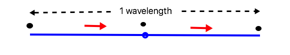
We start the same way, with minimum current at the ends. If we start at one end, we again have a current maximum (arrow) 1/4 along the wire, then a minimum at the feedpoint. We get the same thing starting from the other end, but we can’t just assume a particular direction for the arrow: it has to be the same as the one on the other side of the feedpoint.
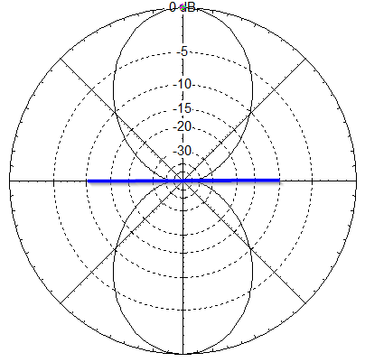
The result is that we have two half wave radiators, with the current in phase, so they will add in the direction of the reader. Because the feedpoint is at a current minimum (a dot), the feedpoint impedance will be high. Because there are two radiating portions in phase along the length of the wire, we get some colinear gain, making the pattern narrower than a half wave dipole. Like this:
What happens if we look at the same wire, but move the feedpoint?
If we start at the left end, this is just like a dipole, the feedpoint is 1/4 wavelength from the end, so it is at a current maximum arrow. (In practice, the feedpoint could be moved along the wire and we would still get the same effect, as long as it wasn’t too close to the center.)
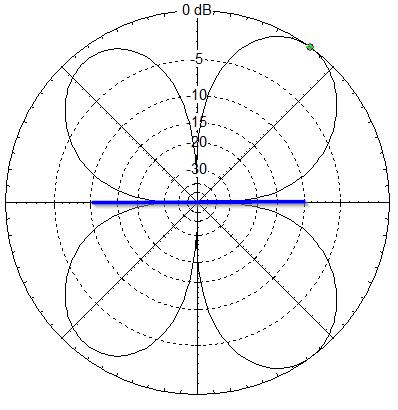
But when we start from the right side, we have a current minimum, a maximum, another minimum, then reach the feedpoint at a maximum 3/4 wavelengths from the end. To determine the arrow directions we have to start at the feedpoint: the portion beside the feedpoint has the same direction as the existing arrow, but the adjacent section on the left has the arrow reversed because of the phase change in adjacent segments. The two arrows are now out of phase, so they cancel in the direction of the reader. This means there is a null broadside (perpendicular) to the antenna wire. Because there is also a null directly off the ends of a wire, maximum radiation is between the two directions, roughly at 45 degrees to the wire. (Actually, about 55 degrees.) Something like this:
Again, because we are feeding it at a point of maximum current, the feedpoint impedance will be relatively low – typically 90 ohms or so.
One more example, and we will try to make it a bit more interesting. Let’s look at a delta loop with each side 1/2 wavelength long, fed in one corner:
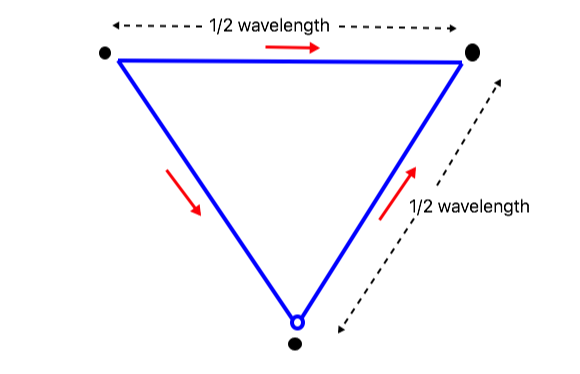
Because this is a closed loop, we start with an arrow (current maximum) in the middle of the top wire – that is half way around the loop from the feedpoint. Current is minimum at the corners, and there are maximums in the middle of each of the other two sides. Notice the arrow directions: the arrows point in the opposite direction along the wire as the top arrow, but because the wire is bent around the corner, it also changes direction, and the overall effect is that the arrows point in somewhat the same direction.
If we look at the arrows from an “up” and “down” perspective, the top arrow contributes nothing (it is horizontal), and the two lower arrows are equal and opposite, so there is little or no vertically polarized radiation from this antenna in the direction that we are viewing it from. But considered horizontally, all the arrows are generally pointing from left to right, so they will be in phase for horizontal polarization. In fact, the 3/2 wavelength loop gives the greatest broadside gain: as the loop is made any larger, the gain drops off, as will become apparent if you run the same analysis for a square loop 1/2 wavelength on a side.
This simplified analysis doesn’t replace antenna modeling software, of course, and there are some things like load resistors or parasitic elements that it doesn’t handle well. But it works well for antennas like the Bruce, Sterba, Bobtail curtain, half-square, bi-square, and end-fed wires for NVIS operation. I have found it very helpful over the years for understanding why an antenna had a particular radiation pattern, while others that seemed similar radiated in a different direction. And, with practice, you can do it in your head while looking at a drawing of an antenna and get a much better understanding of how it is going to work.