Construction of Wire Loop Antennas
last updated 4 August 2023.
There are a few basic construction methods for wire loop antennas:
- stiff wire (mostly self supporting)
- strung wire (on a framework of some sort)
- hung from trees, masts, or other supports
None of these need to be particularly difficult to build, although multi-element versions at HF can be mechanically complex.
Stiff Wire antennas
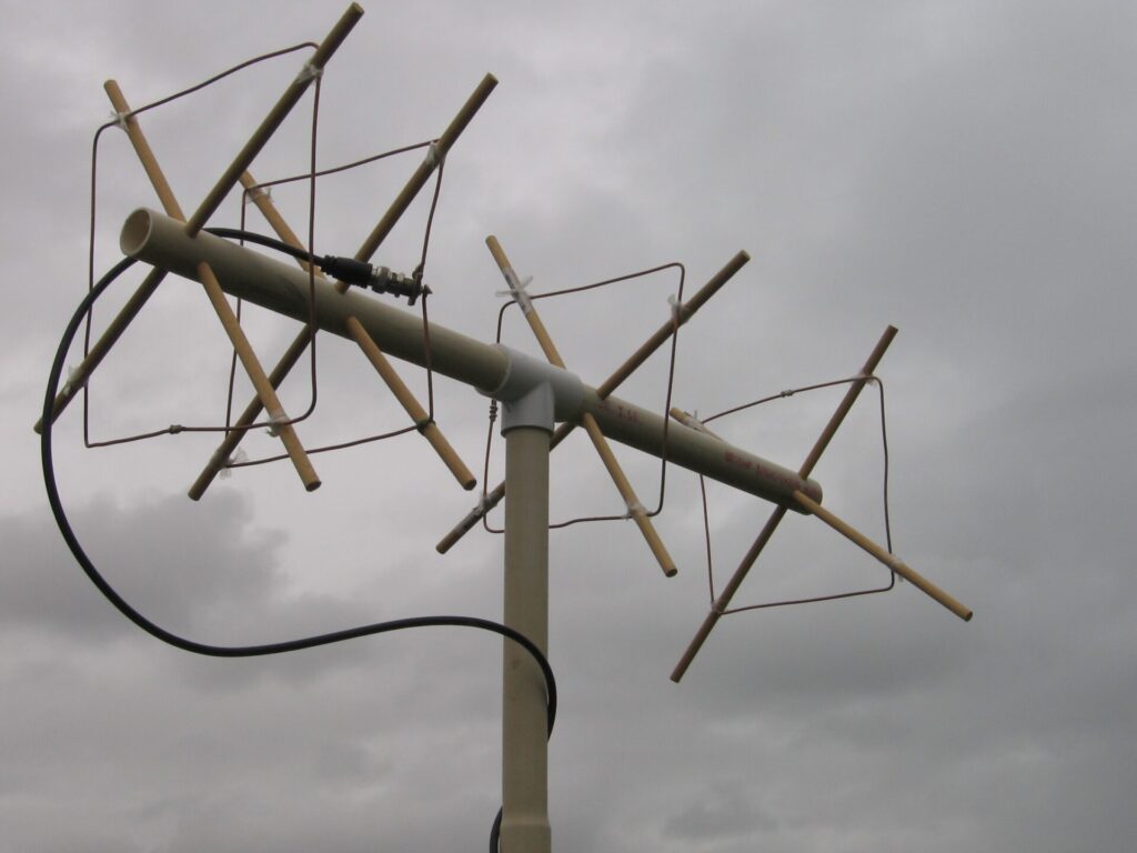
Solid wire in the 1.5mm to 4mm (AWG #6 to AWG #14) range is often stiff enough to be used with minimal supports at VHF / UHF. Figure 1 shows a cubical quad for 2m, where a single horizontal piece of plastic water pipe supports the whole element. In fact the whole support frame is made of plastic pipe, and the elements can be removed from the boom to save space.
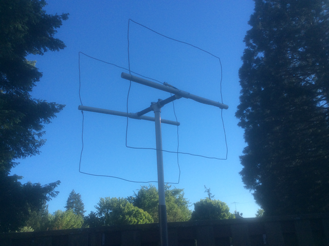
I use this antenna sticking out the window of my car for mobile transmitter hunts and other radio direction-finding activities: many times the element has been bent by driving into tree branches, but the wire can usually be straightened by hand with no permanent damage.
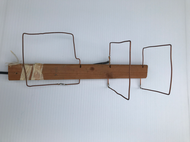
The method shown in Figure 2 is usable at UHF (in this case, 732 MHz), and allows the elements to be folded flat against a wooden handle.
Such antennas are less suitable below about 100 MHz when using 2mm (AWG #12) copper wire, as it is not strong enough to hold up (especially when driving at high speeds). Aluminum or copper tubing can be used similarly on lower frequencies. I prefer the Strung Wire approach below about 120 MHz.
Strung Wire antennas
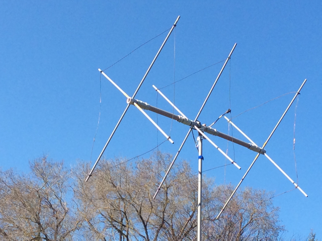
These use a rigid framework that supports all parts of the wire, and can use a thinner or more flexible wire for the element. This is the common construction method for rotatable quad antennas below the 2m band (including HF). For multi-element antennas there are two common methods: either use a standard boom with spreaders for each element in a flat plane, or angle the spreaders out from a common hub attached to the mast. The latter approach allows elements for multiple bands to be supported on a single set of spreaders with relatively constant spacing as a function of wavelength, but is somewhat more complex to build. For long boom designs, flat spreaders are used, with the element spacings adjusted where possible to put elements for two or more bands on a single set of spreaders.
Spreaders are often fiberglass fishing rods for larger HF quads. Any metal in the framework should not be too close to the element, and shouldn’t be resonant on the desired bands. Using metal angle stock on the hub that connects to the boom, then attaching fiberglass or bamboo spreaders to that, seems to work well.
Many hams drill and pass the wires through the spreaders, but this requires careful calculation of the position and doesn’t allow much variation for tuning. Also, the wire rubbing where it passes through the spreader can cause failure. Such holes can weaken a fiberglass spreader. Often a better approach is to attach the wire with some sort of clip or clamp, or a short piece of rope, that allows it to be moved up or down the spreader (or even removed) if needed. Passing the wire through some sort of insulator, or plastic tubing, where it attached to the spreader helps to reduce abrasion.
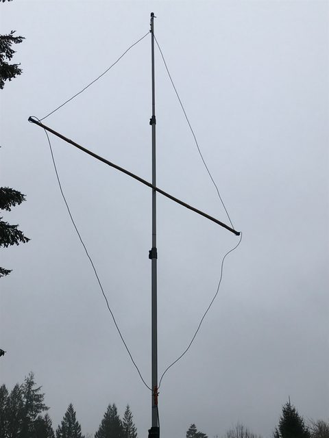
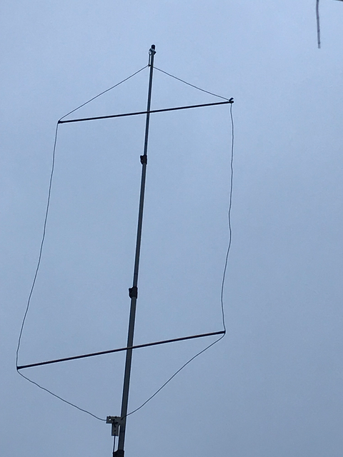
There some less traditional methods that can work for single element loop antennas. For example, Figure 6 shows a vertical wire loop with a single horizontal spreader, which is often (but not always) attached to the mast. The loop is hung from the top, and the weight of the feedline at the bottom keeps the loop in shape. A hexagon loop with two such spreaders is shown in Figure 7. This is sometimes more practical than a rectangular loop.
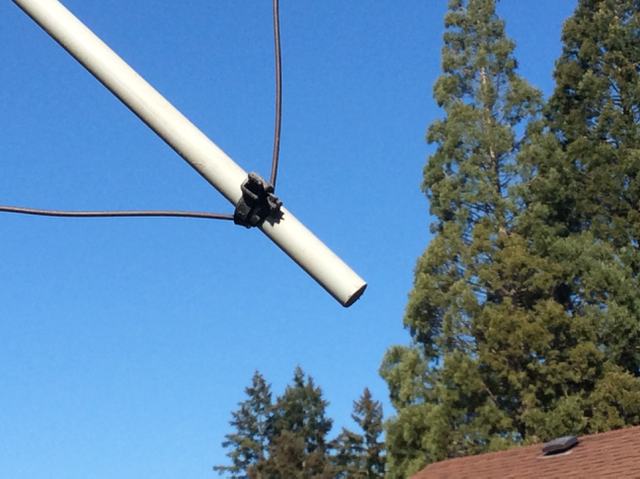
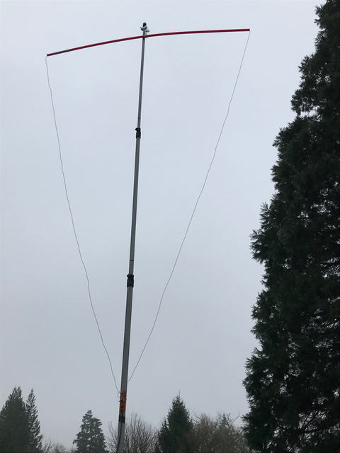
A delta loop can be supported by a single top spreader: Figure 8 shows a wire passed through a length of plastic pipe (which may affect the tuning somewhat). If aluminum tubing is used for spreaders, it can form the top and/or bottom elements with wires for the vertical portions. (Due to the typical difference in conductor sizes, this will require a bit more length for the same resonant frequency than using wire alone.)
Larger Fixed Loops
Wire loops for the lower bands are often strung from trees or masts, either in the vertical plane or horizontally. The article on Building a Simple Wire Dipole discusses many common approaches that can be used, and this section will address just those parts that may be different when installing loop antennas.
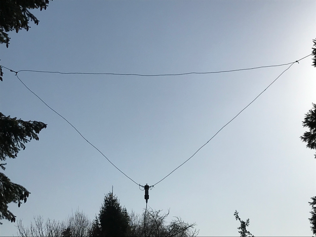
As explained in Full Wave Loop Antenna Theory, the proportions of a loop can be modified (with little change in wire length) to vary the feedpoint impedance. The delta loop with the point down is particularly useful in this way: when designed for a 200 ohm impedance it gives a wide operating bandwidth, and can be strung between two trees like a dipole, but without the center of the wire having to support the weight of the feedline, as shown in Figure 9.
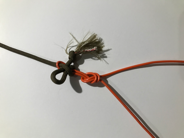
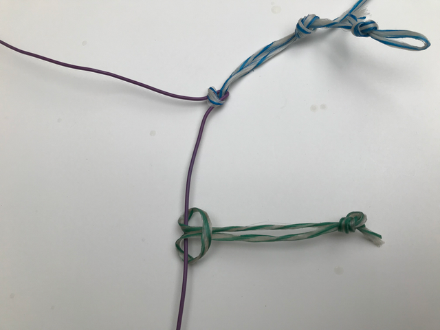
I typically tie a loop knot for the support ropes at the the calculated distance across the horizontal portion. As the impedance varies with height, I can move these in or out to improve the match. This is a great antenna to feed with a quarter wave of 100 ohm line, and the dimensions can be adjusted as needed if the impedance of the matching section is a bit higher or lower. In some cases it may be sufficient just to tie the ropes to the wire without the loops to make it easier to adjust the length of the top wire for the desired feedpoint impedance. Figure 11 shows one way to tie the loop corners so that the knot can be moved along the wire without having to retie it.
The delta with the point up is often used for vertical polarization, and again the feedpoint impedance varies with the width of the loop vs. the height. Because there is much less stress on the bottom wire, tied loops for the corners may not be needed.
One approach that can be helpful for both the vertically polarized delta and large horizontal loops is to use a “floating” insulator tied to a rope that can move along the wire as needed. This is particularly useful when installing a horizontal loop with randomly spaced trees, where the actual locations of where the support ropes connect may not be exactly known. I like to use plastic “egg” insulators (or “compression insulators”) from electric fences for this purpose, as they slide easier than some other types (though the wire insulation makes a difference in that regard, too).
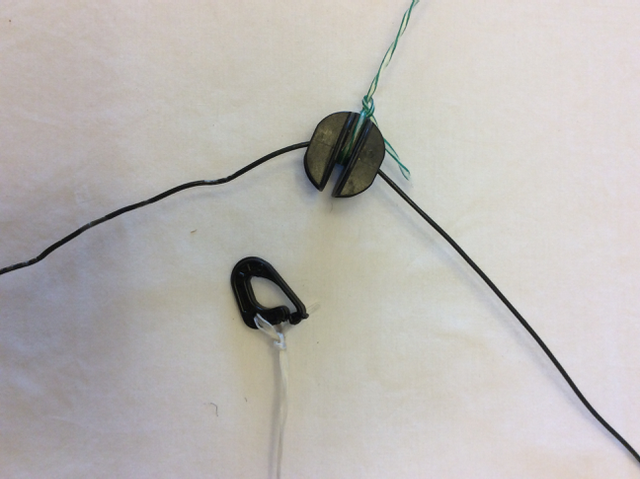
For larger horizontal loops, my favorite method is to lay the wire out on the ground about where I want it to go, throw a rope over whatever trees or other supports are convenient, attach the rope and insulator around the wire (there is a slot in these insulators so the wire need not be threaded through a hole), then pull up the ropes a bit at a time and let the loop sort itself into whatever shape it wants to. If an insulator gets caught in an awkward spot, then some loosening and tightening of the support ropes will often encourage it to move. It is quite possible to do this even with other trees in the center of the loop. Even with intentional support masts installed for the purpose, there should be some space between the mast and the expected corner of the loop (perhaps 2m / 6 feet or more).
Note that, while most reference books show such loops as regular polygons, they still work well in irregular shapes, often in both vertical and horizontal planes, to take advantage of whatever supports are available. For example, the wire can be installed under the eaves of a house using electric fence insulators, staples or plastic clips, or run between poles nailed to fence posts. Because the wire opposite the feedpoint will always be a high current point regardless of loop length, it may be worthwhile trying to arrange for that to be the highest point by adjusting the feedpoint position if that is convenient.
When it isn’t convenient to adjust the loop length for resonance, the loop may be fed with ladder line or twinlead to a tuner and used on multiple bands.
In dense woodland, a loop may have to be threaded through the branches by throwing a rope through and pull the wire after it, as many times as is needed around the perimeter. In such cases there is no expectation that the loop wire length will come out as expected, unless there is an adjustable corner in the loop that can be used to take up or let out length.
Even a full wave loop for 80m is relatively easy to measure using a Wire Measuring Board.