Theory of Full Wave Loops
last updated 28 November 2023.
Definition
A full wave loop is, as the words imply, a continuous loop of wire or other conductor approximately one wavelength long, usually with the two ends of the loop connected to the feedline.
The exact length for resonance depends on the diameter of the conductor and the shape of the loop, but typically it is slightly longer than a physical half wavelength at the resonant frequency. A traditional formula for the length in meters is 306 / MHz (or 1005 / MHz in feet), but, like the similar formula for a dipole, this must be considered only an approximation. Unlike dipoles, larger diameter conductors require a larger circumference for resonance.
Full Wave Loop Characteristics
The full wave loop forms a second basic building block of antennas, along with the the half wave dipole. In fact, the two are similar in many ways: the full wave loop can be thought of two dipoles with the ends connected together, or a folded dipole opened up into a 2-dimensional shape.
Compared to a half wave dipole, a full wave loop has a bit of broadside gain due to the separation between the two wires, though that is lessened slightly due to the shortening effect of bending the ends so they join.
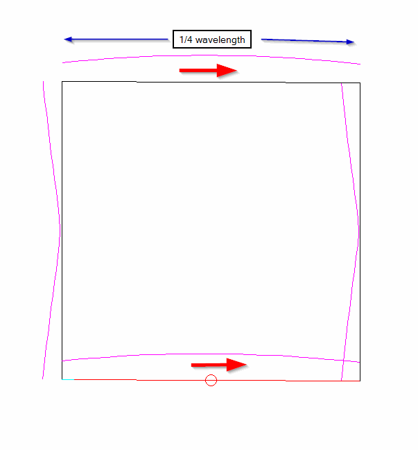
The current on a full wave loop antenna is maximum at the feedpoint, and at the point of the loop opposite the feedpoint. Current is minimum at the points midway between those two. Due to the phase reversal along the wire, the currents are in phase when viewed broadside to the loop.
Maximum radiation is broadside to (perpendicular to the plane of) the loop, unlike small loops which have a null in that direction.
In general, closed loops between about 2/3 wavelength and 3/2 wavelength in circumference will have maximum radiation in the broadside direction. Larger loops may have a broadside null, depending on the shape and length.
Effect of different loop shapes
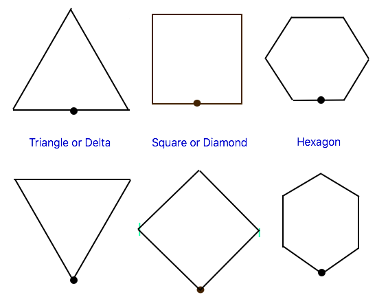
The full wave loop is most frequently constructed as a square or diamond for mechanical simplicity. Other regular polygons are sometimes used, such as a triangle (called a “delta loop”, after the triangular Greek letter) or a hexagon. In practice the loop need not be a regular shape at all, but such shapes are easier to analyze.
In theory, a perfect circle would have slightly more gain than a regular polygon, but the additional mechanical complexity (especially at HF) generally is not worth the extra 0.3 dB or so of gain. (Moving from a square to a hexagon will make up much of that difference.)
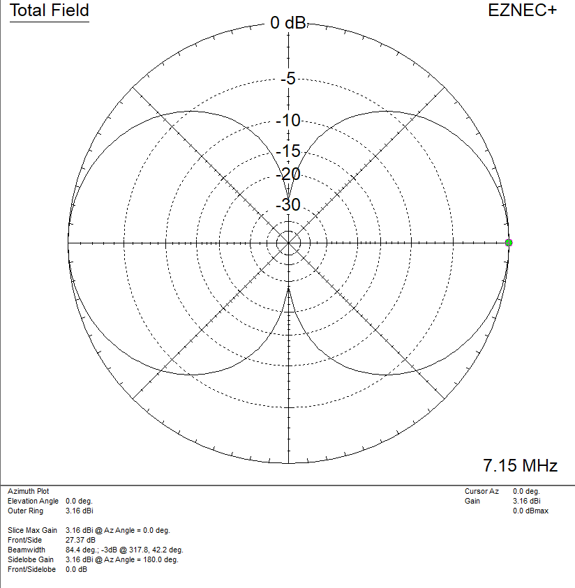
If we look at the radiation patterns of regular polygons in free space, fed either at a corner or in the center of one side, there is not a lot of practical difference among them:
| polygon | feedpoint | gain dBi | impedance |
| triangle | corner | 2.79 | 121 ohms |
| triangle | side | 2.96 | 115 ohms |
| square | corner | 3.19 | 129 ohms |
| square | side | 3.30 | 126 ohms |
| hexagon | corner | 3.43 | 134 ohms |
| hexagon | side | 3.48 | 132 ohms |
| octagon | corner | 3.51 | 136 ohms |
| octagon | side | 3.54 | 135 ohms |
So in free space, feeding a regular polygon loop in the middle of one side gives slightly more gain and slightly lower feedpoint impedance than feeding it at a corner, and the difference becomes smaller as the number of sides is increased. (In a later section we will consider other shapes, and the impact on mounting such antennas over ground, which can have a significant impact on these conclusions.)
The range of gains across all variants is less than 1 dB, and the improvement beyond a square is fairly small. By comparison, the gain of a half wave dipole is about 2.15 dBi, so in general loops give about 1 dB additional gain. In practical applications, we will see that the loop shape will be driven more by support considerations than for free-space gain.
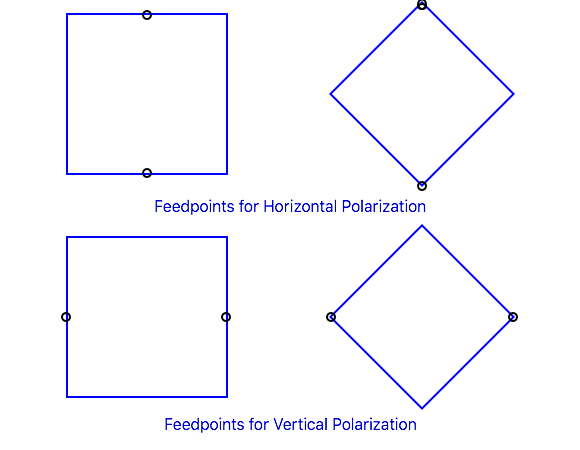
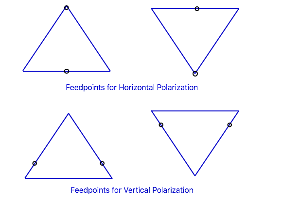
Effect of feedpoint position
The position of the feedpoint around the loop determines the polarization. Feeding the loop at the bottom or the top gives horizontal polarization. Feeding it in the center of one side, so the current minima are at the top and bottom centers, gives vertical polarization. With some loop shapes the required feedpoint position might not be exactly at a corner or in the middle of a side: for example, with an equilateral triangle with the base down and one corner up, the feedpoint for vertical polarization is 1/4 of the wire length down from the top corner, which will be a little ways up from the bottom corner.
In general for any balanced loop, current is maximum at the point opposite the feedpoint. In this case, when the conductor is a full wavelength, there is a second current maximum at the feedpoint.
Other Loop Shapes
Most descriptions of full wave loops stop with regular polygons, but if we let go of that limitation we find a lot of other possibilities.
We can stretch a square loop into a rectangle and get a sense of the possible variations. In the following table, the loop is 20m in circumference with the feedpoint at the bottom (still in free space), but the lengths of the sides can vary from “short and wide” (basically a folded dipole) to “tall and skinny”: (Note: in the following tables, the numbers are for one specific set of conditions, but the general trends should apply to other situations.)
| height (m) | width (m) | resonant frequency (MHz) | gain dBi | impedance (ohms) | 2 : 1 SWR bandwidth (MHz) |
| 1 | 9 | 14.7 | 2.2 | 280 | 1.8 |
| 2 | 8 | 15.1 | 2.3 | 262 | 1.85 |
| 3 | 7 | 15.45 | 2.5 | 226 | 1.7 |
| 4 | 6 | 15.7 | 2.8 | 178 | 1.4 |
| 5 | 5 | 15.8 | 3.3 | 125 | 1.0 |
| 6 | 4 | 15.8 | 3.8 | 76 | 0.6 |
| 6.67 | 3.33 | 15.75 | 4.1 | 50 | 0.4 |
| 7 | 3 | 15.7 | 4.5 | 39 | 0.3 |
| 8 | 2 | 15.5 | 5.2 | 15 | 0.12 |
| 9 | 1 | 15.275 | 5.6 | 3 | 0.03 |
There is a lot to process here. First, the feedpoint impedance, gain, and resonant frequency vary with the shape of the loop, even though the wire length is held constant. We can adjust the shape to get any desired feedpoint impedance from about 300 ohms to 50 ohms, or a bit lower.
This is a good example that the perimeter of a loop is not a fixed constant for a particular resonant frequency, and that all full wave loops do not have the same feedpoint impedance. These are common misconceptions.
(The last two entries in Table II are probably impractical without using very fat wires, due to the low feedpoint impedance and narrow bandwidth. The actual gain will be limited by the resistance of the wires.)
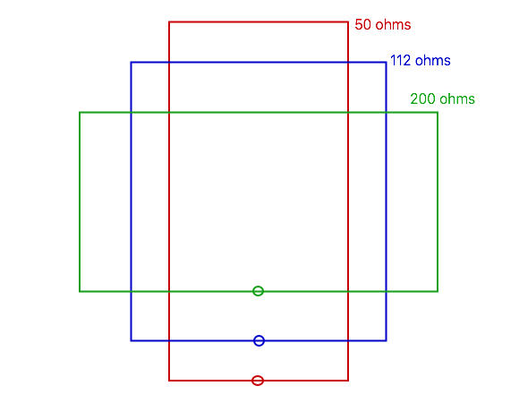
When the loop is about twice as tall as it is wide, we get a good match to 50 ohms, and additional gain: in fact, this shape (as well as the line above it that matches 75 ohm coax) have higher gain than we would get using a circular loop. Other useful impedances are 112.5 ohms (to match with a quarter wavelength of 75 ohm coax) or 200 ohms (to match with a 4 : 1 balun, or a quarter wavelength of 100 ohm balanced line: a pair of 50 ohm coax cables side-by-side, or standard American 2-conductor electrical cord is about 105 ohms).
But don’t lose sight of the last column: the SWR bandwidth. The 50 ohm loop can just cover the 20m band at a 2 : 1 SWR, but when used as a portable antenna any variation in setup may shift the curve so it is no longer centered in the band. The 75 ohm loop, while having 0.3 dB less gain, would cover most of the band at about 1.5 : 1 or less, and allow for more variation without needing to retune the loop. (The 1.5 : 1 SWR bandwidth is about 0.55 times the 2 : 1 bandwidth.) A 200 ohm loop covers the whole band under 1.3 : 1.
While this table is specifically for rectangular loops, the same principles apply to other shapes: as the far side is stretched further from the feedpoint, the gain increases and the feedpoint impedance and SWR bandwidth decrease. Those also apply when the loops are used in parasitic arrays such quad or delta loop beams. This ability to adjust the feedpoint impedance by changing the shape of the loop (with relatively small changes in loop wire length) gives us a lot more flexibility in designing and building antennas.
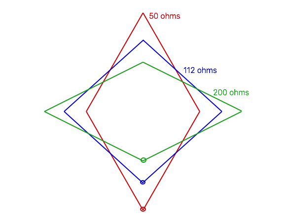
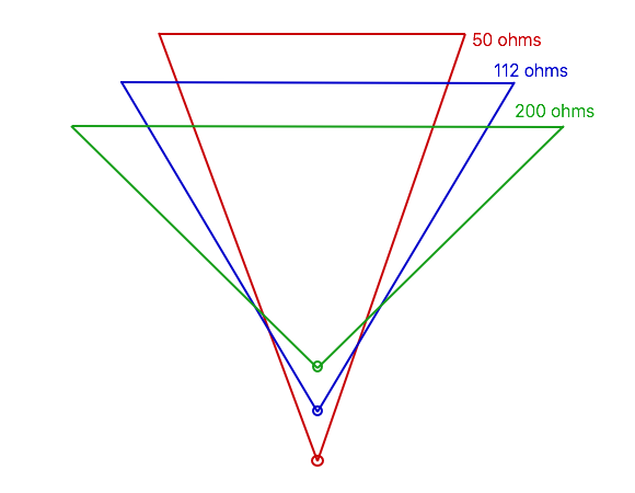
Note: I have drawn Figures 6, 7, and 8 to scale, as well as I can. If you measure the dimensions on your computer screen or a printout and scale it to the expected wire length for the desired frequency, you should have a good starting point.
We now have lots of options, but note some of the quirks. Simply knowing the length of wire in the loop is not enough to determine the resonant frequency. Comparing the 2+8 and the 8+2 entries in Table II, the resonant frequency varies with the feedpoint location even for same physical shape. And things change further when we consider the behavior of the antenna over ground.
Full Wave Loops over Ground
While free space works reasonably well for modeling the relative performance of VHF/UHF antennas in many cases, it can give misleading results for HF antennas, particularly those at heights less than 1 wavelength. But the ground has a different effect depending on the orientation of the antenna, so we will divide the discussion into 3 sections because the behaviors can be quite different:
- Horizontal full wave loop antennas over ground
- Vertically polarized vertically oriented loop antennas over ground
- Horizontally polarized vertically oriented loop antennas over ground
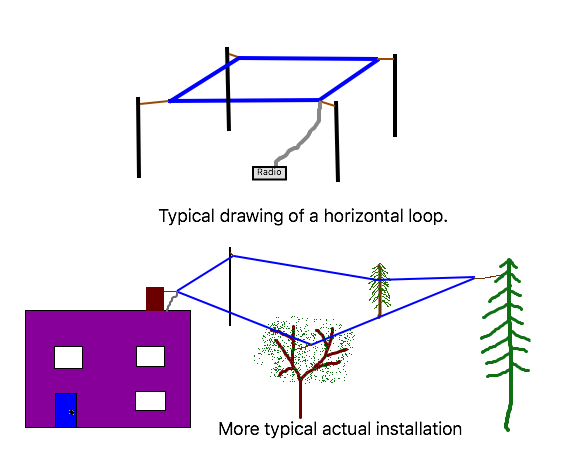
Horizontal full wave loop antennas over ground
When a full wave loop is erected horizontally at relatively low heights (sometimes called a “sky loop” or similar), maximum radiation is still broadside to the loop, or straight up. This isn’t particularly good for the low angles of radiation favored for DX, but it can make an excellent NVIS antenna for local contacts on the lower HF/MF bands (40m, 60m, 80m, and 160m) when operating below the critical frequency. The ground acts as a reflector, which improves signal strengths at some heights. Typical heights are below about 1/3 wavelength, and it can still work at 0.05 wavelengths, though ground losses are becoming more of an issue at low heights.
Here is some modeled data for a full wave square loop fed in one side at various heights over poor ground (it will vary with ground characteristics):
| height (wavelengths) | feedpoint impedance (ohms) | maximum gain (dBi) | angle of maximum gain | gain at 90 degrees (dBi) |
| 0.5 | 110 | 6.4 | 30 | -3.9 |
| 0.4 | 143 | 5.6 | 40 | 1.5 |
| 0.35 | 156 | 5.5 | 48 | 4.1 |
| 0.3 | 160 | 5.7 | 63 | 5.5 |
| 0.25 | 152 | 6.4 | 86 | 6.4 |
| 0.2 | 136 | 6.7 | 90 | 6.7 |
| 0.15 | 115 | 6.4 | 90 | 6.4 |
| 0.125 | 105 | 5.9 | 90 | 5.9 |
| 0.1 | 97 | 5.0 | 90 | 5.0 |
| 0.075 | 95 | 3.6 | 90 | 3.6 |
| 0.05 | 101 | 1.2 | 90 | 1.2 |
| 0.025 | 125 | -2.4 | 90 | -2.4 |
Peak gain overhead is around 0.2 wavelengths, but performance is relatively constant from about 0.1 to 0.30 wavelengths for short NVIS paths (radiation straight up). Above 0.35 wavelengths an overhead null develops due to the ground reflection. Below about 0.1 wavelengths we see the effects of ground losses, though a loop around the top of a fence or under the eaves of a house can still be effective, even if not optimum. It need not be a regular polygon, and can run from one support to the next, using whatever is available.
Impedances are in a reasonable range to be matched with a 4 : 1 balun or a quarter wave of 75 ohm coax (target impedance 112.5 ohms). However, note that the impedance will change with ground characteristics, especially at the lower heights, as well as the feedpoint location on the loop.
These data probably will not exactly match your specific installation, but they give an idea of what sorts of variation to expect.
In practice, a horizontal full wave loop is popular as a multi-band antenna, since the angle of radiation lowers on higher bands, giving good performance on longer paths. But at that point the loop is no longer one wavelength, so I have a separate article to discuss such antennas.
Vertically Polarized Vertically Oriented Full Wave Loop Antennas Over Ground
Yes, it is a mouthful, but all those qualifiers help to define the antenna we are discussing here: a full wave loop in the vertical plane, fed in the middle of one side for vertical polarization, considered over ground.
Performance in many ways is similar to the same antenna in free space. The two major considerations are the effect of the ground on the radiation pattern, and capacitive coupling between the ground and the high impedance point at the bottom of the antenna. Height above ground generally is less important for vertical polarization, where radiation at low angles is more dependent on the ground characteristics instead.
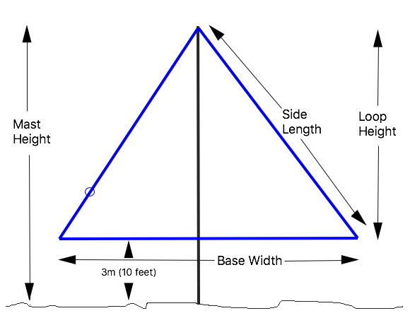
Vertically polarized loops are most often used at relatively low heights on the lower HF bands to take advantage of good low angle radiation for working DX. This is most effective over high conductivity soils, and especially operation over (or near) salt water. For vertical polarization, the loop is fed in the center of one vertical side, or more precisely, 1/4 of the wire length from the top (and bottom) centerline of the antenna. For a square or rectangle, this is the middle of a vertical side, as shown in Figure 4. For a diamond, it is in one side corner. For a triangle, it is 1/4 of the wire length from the apex, whether it is pointing up or point down, as shown in Figure 5.
Because the bottom center of a vertically polarized full wave loop is a high impedance point, it is more prone to capacitive coupling to the ground, causing a larger shift in resonant frequency due to the height of the bottom wire and the current distribution around the loop. It can also increase ground losses under some conditions. Most often what we see is that the resonant frequency shifts compared to the same loop in free space, so dimensions will vary more depending on height and configuration. For example, while a 50 ohm rectangle in free space has about a 2 : 1 ratio of side lengths, this will increase to between 2.5 : 1 and 3 : 1 or so when the short side is vertical and the long side is parallel to the ground (and will vary with height).
The most popular shapes for vertically polarized full wave loops are the rectangle (often stretched horizontally, so it doesn’t require as much height), and the triangular (delta) loop with a point up, as it only requires one tall support. When fed properly for vertical polarization, the loop has an overhead null that helps to reduce QRM from local stations.
There often is a trade-off between height and width of the loop, depending on what supports are available. We can look at what impact this has on a delta loop hanging from a single support if we keep the wire length constant at 45m (148 feet) and the base 3m (10 feet) above ground, then vary the length of the base and the resulting height of the loop.
| base width m (feet) | loop height m (feet) | side length m (feet) | mast height m (feet) | freq (MHz) | imped- ance (ohms) | max gain (dBi) | max angle (deg.) | gain at 10 deg. |
| 22 (72) | 3.4 (11) | 11.5 (38) | 6.4 (21) | 7.20 | 11 | 1.7 | 26 | -0.6 |
| 21 (69) | 5.8 (19) | 12 (39) | 8.8 (29) | 7.13 | 30 | 1.9 | 25 | -0.5 |
| 20 (66) | 7.5 (25) | 12.5 (41) | 10.5 (34) | 7.10 | 48 | 1.8 | 24 | -0.5 |
| 19 (62) | 8.9 (29) | 13 (43) | 11.9 (39) | 7.08 | 69 | 1.7 | 23 | -0.4 |
| 18 (59) | 10.1 (33) | 13.5 (44) | 13.1 (43) | 7.08 | 91 | 1.6 | 23 | -0.5 |
| 17 (56) | 11.2 (37) | 14 (46) | 14.2 (47) | 7.05 | 115 | 1.4 | 22 | -0.5 |
| 16 (52) | 12.1 (40) | 14.5 (48) | 15.1 (50) | 7.06 | 138 | 1.3 | 22 | -0.6 |
| 15 (49) | 13 (45) | 15 (49) | 16 (52) | 7.05 | 161 | 1.2 | 21 | -0.6 |
| 14 (46) | 13.8 (45) | 15.5 (51) | 16.8 (55) | 7.04 | 188 | 1.0 | 21 | -0.7 |
| 13 (45) | 14.6 (48) | 16 (52) | 17.6 (58) | 7.04 | 212 | 0.9 | 20 | -0.8 |
| 12 (39) | 15.4 (51) | 16.5 (54) | 18.4 (60) | 7.02 | 235 | 0.8 | 20 | -0.8 |
| 11 (36) | 16 (52) | 17 (56) | 19 (62) | 7.02 | 257 | 0.7 | 19 | -0.9 |
| 10 (33) | 16.8 (55) | 17.5 (57) | 19.8 (65) | 6.96 | 280 | 0.6 | 19 | -0.9 |
Probably the most important thing to learn from this table is that the low angle radiation at 10 degrees (the last column) doesn’t change much as the loop is made taller and narrower. The widest / shortest version may not be practical due to the low feedpoint impedance, but mast heights of about 0.2 to 0.35 wavelengths are adequate to give good performance at impedances that are convenient to match to 50 or 75 ohms. (115 ohms would use a quarter wave transformer of 75 ohm coax.)
Note that the center of the bottom wire is a high voltage point: voltages are not as high as at the ends of a dipole, but it is still good practice to keep the bottom wire well out of reach of anyone walking by. If suitably protected, the bottom wire can be placed closer to the ground to reduce the required mast height – expect a bit of change to the loop length and possibly slightly higher ground losses.
Some hams find it more convenient to feed such a loop in a bottom corner rather than part way up one side. This works relatively well for the shortest loops where the side length isn’t much longer than 1/4 of the wire length, but as the side length increases with height the amount of horizontally polarized radiation increases. Gain at low angles is typically 0.3 dB lower, but the major effect often is the increase is response to signals arriving at high angles. For the loop with the 17m base, the radiation straight up is only 6 dB lower than that at low angles, so interference from local stations at high angles will be more significant.
Any of these loops can be switched between vertical polarization (for DX) and horizontal polarization (for more local contacts) by putting pulleys on the corners of the wire, allowing the feedpoint to be moved to the top corner of the loop by pulling on the wire (or to the bottom center, if you can get it past the corner pulley). This has two impacts on matching: the feedpoint impedance changes, and the resonant frequency drops. The feedpoint impedance change is minimal for impedances in the 120 – 140 ohm range, but increases away from that. The loop with the 20m base length, for example, is very close to 50 ohms for vertical polarization, but almost 200 ohms for horizontal polarization. The frequency shift in this case is around 400 kHz, and 100 kHz for an equilateral triangle (15m base length). Nevertheless, it can be a convenient method of converting one antenna to serve both functions.
Horizontally Polarized Vertically Oriented Full Wave Loop Antennas over Ground.
The Earth has the same effect on loops as on any horizontally polarized antenna: it acts as a reflector, and the far field is determined by the relative strength and phase of the direct and reflected waves. While there is enough radiation off the sides of the loop to make a useful NVIS antenna on the lower bands, this is particularly important for radiation at low elevation angles that work best for DX.
When we looked at the effect of antenna height for a dipole antenna, the antenna had a specific height. With a full wave loop, we now have two different heights, the top and the bottom for a rectangular loop, or their equivalents for other shapes. Each of these radiates about the same power, but they are at different heights above ground, so they contribute differently to the resulting pattern.
One approach to analyzing this is to calculate the height of average current in an antenna. For a square / diamond and many other regular polygons, this is just the center height of an antenna. For a triangle, or “delta loop”, it is about 1/3 of the distance from the base to the opposite vertex (because the straight side with a current maximum will contribute more than where the wire is bent at a corner). It turns out that, while this doesn’t give the same exact result, it gives us an idea of what to expect.
One problem with this arrangement is that our supports are often at a fixed height, and the question then is how to maximize low angle radiation given the available support height. Let’s repeat the analysis of the 20m perimeter rectangular loop with a fixed top height of 12m over “typical” ground, looking not only at the angle of maximum radiation, but also the signal strength at a vertical angle of 10 degrees, representative of some DX paths:
| width (m) | height (m) | gain (dBi) | angle of maximum gain (degrees) | gain at 10 degrees (dBi) |
| 9 | 1 | 7.8 | 24 | 3.7 |
| 8 | 2 | 7.8 | 24 | 3.7 |
| 7 | 3 | 7.7 | 25 | 3.6 |
| 6 | 4 | 7.7 | 25 | 3.4 |
| 5 | 5 | 7.7 | 25 | 3.4 |
| 4 | 6 | 7.7 | 26 | 3.3 |
| 3 | 7 | 7.6 | 26 | 3.2 |
| 2 | 8 | 7.4 | 26 | 3.0 |
And, for comparison, a dipole at the same height:
| antenna | maximum gain (dBi) | angle of maximum gain (degrees) | gain at 10 degrees (dBi) |
| half wave dipole | 7.9 | 23 | 4.2 |
And a couple of triangular delta loops, with the flat side up and the point down:
| antenna | maximum gain (dBi) | angle of maximum gain (degrees) | gain at 10 degrees (dBi) |
| 200 ohm triangle | 7.7 | 24 | 3.6 |
| 50 ohm triangle | 7.7 | 24 | 3.6 |
Gets pretty repetitious, doesn’t!
In this case, none of the loops did as well as a dipole at the same top height, but they were close enough that it would be difficult to detect any difference in actual usage, including the triangular loops that had the lowest gain in free space. That is because, while the free space gain increased with the spacing between the top and the bottom, the bottom wire (radiating half the power) doesn’t contribute as much to the low angle radiation. The triangular loops, with the flat side up have a higher average height, and are often easier to install using the same supports as for the dipole.
In this particular case, there isn’t much significant difference in gain among the various loop options, and the dipole is better than any loop (by a very slight amount) when the top height is fixed. That situation will change with height: as the antenna height is increased, so the bottom wire contributes more to low angle radiation, some of the loops will eventually be better than the dipole due to the higher gain. At a height of 1 wavelength, the 3m wide x 7m tall loops shows over 1 dB of gain over a dipole. The range around 1/2 wavelength (including 0.6 wavelengths, which corresponds to the preceding table) is about the point where the loops and dipoles are equivalent: above that point, loops will begin to show higher gain, while below it the bottom wire contributes less and the loops will not show as much gain.
In general, to give significant gain over a dipole for low angle radiation, a broadside antenna (including loops) needs to have the top around 1 wavelength, and the bottom at least 1/2 wavelength above the ground
So why would we want to use a loop when a dipole is slightly better? There are several reasons:
- The 200 ohm delta loop has a wider SWR curve than the dipole, and the dimensions can easily be adjusted for the variation in loop impedance with height to give a nearly perfect match.
- The 50 ohm delta loop is only 5m across the top, compared to 10m for the dipole. This allows the antenna to fit between supports that don’t have room for a dipole.
- With a dipole strung between two supports, the weight of the balun and feedline are in the middle of the wire, requiring more tension and/or more sag in the antenna. With a delta loop the coax is shorter, and the weight of the balun and feedline are supported by diagonal wires hanging from the support ropes rather than from the center of the wire span. Mechanically this may be a better solution in some situations.
- When using a very light support mast, such as a telescoping fishing pole, the tip section may not support the weight of the feedline and antenna, but can handle a light wire as a loop, with the feedpoint further down the mast where it is stronger. A vertical loop makes a good NVIS antenna for the lower bands even if it isn’t very high, and feeding it at the bottom reduces the required feedline length.
- Even though the low angle radiation may not be any better than a dipole, an elongated loop narrows the vertical pattern, and can reduce the strength of signals coming in at higher angles, making it easier to hear the DX through the QRM.
All of these, however, depend very much on the specifics of the installation, especially the height, spacing, and strength of the available supports, as well as the required vertical angle to target location, and may require modeling and/or experimentation.
continue to: practical antenna dimensions
BACK TO:
RELATED LINKS:
current distribution along a wire