The Half Wave Dipole
last updated 18 August 2023.
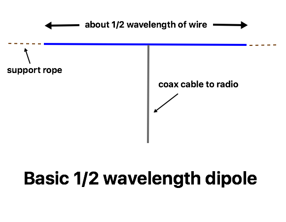
The half wave dipole is not only one of the most simple and common antennas, but it also forms a basic building block for many other types. This is a common drawing of one:
But that really isn’t too practical – you can’t get it perfectly horizontal when supported by ropes on the ends, as the weight of the wire and feedline will make it sag in the middle. Don’t worry, it still works. In fact, it can be installed in many different ways. One of the most common (at least for wire antennas) is the “inverted vee”, as it only requires one high support.
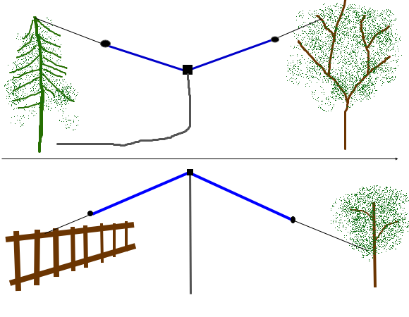
Dipoles for higher frequencies can be built from rigid elements like aluminum tubing or rod, copper pipe, stiff wire, etc.
One big advantage of a dipole is that, in most cases, the feedpoint impedance is suitable for direct coax feed. While the nominal impedance of a thin dipole in free space is 72 ohms, the actual impedance varies with height above ground and other factors, but usually direct feed with 50 ohm coax gives a reasonable SWR that can be used without a tuner on the design band, once the length is adjusted to resonance.
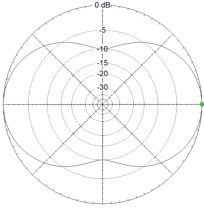
While the radiation pattern in free space shows two main lobes broadside to the wire, with deep nulls off the ends, the main lobes are quite broad (nearly 90 degrees each), which covers half the available directions. The side nulls aren’t nearly as deep when the antenna is at typical heights over ground, especially for shorter paths, so you can still make contacts in most directions.
The overall wire length isn’t exactly one half of a wavelength in free space. It is a bit shorter, due to what is called “end effect”. The “traditional formula” for the length of the wire for a given frequency is 143 / MHz in meters (or 468 / MHz in feet), but the actual required length will vary with a number of factors, so this should just be considered as a rough estimate. In practice, it often is easier to cut the wire a bit long and trim it (or fold it back) to get the SWR centered on your desired frequency. You can estimate the wire length from the wavelength: a half-wave dipole for the 40m band will be about 20 m (65.6 ft) long, of course. While this is useful for estimating size, the band designators aren’t exact, which adds uncertainty, but it is handy for checking your calculations, or for a rough check whether you have room to put it up.
The wire is cut in the center, with one side connected to the coax center conductor and the other side to the coax shield. A balun is a good idea at this point, but don’t let the lack of one keep you from getting on the air. There are many commercial center insulators sold for this purpose, some containing baluns, or you can make your own. Insulators are often used at the ends of the wire, where the voltages can be high, but at power levels up to 100W, plastic ropes are usually adequate.
Further discussion of dipole length