Portable 200 ohm Loop
This antenna often replaces our 40m half wave dipoles for Field Day. The gain and radiation angle aren’t quite as good as a dipole at the same top height (although there is less loss in the shorter coax), but it isn’t quite as wide. And the SWR bandwidth is much better: under 1.3 : 1 or so from 7.0 to 7.3 MHz. We don’t have to worry whether the antenna is tuned for the CW or SSB end of the band, and minor changes due to height and other factors aren’t as much of an issue.
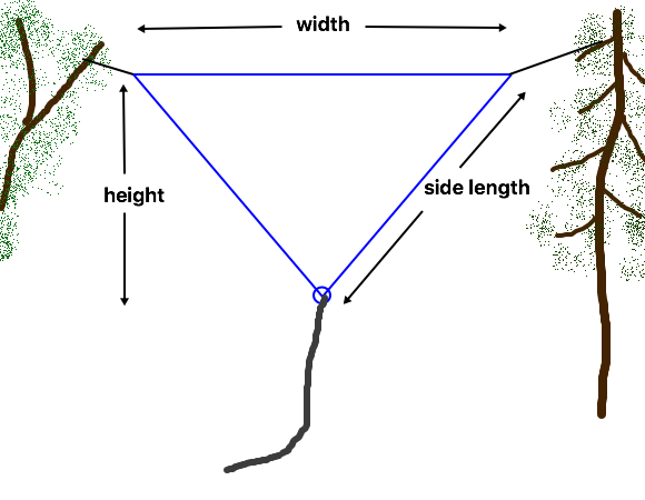
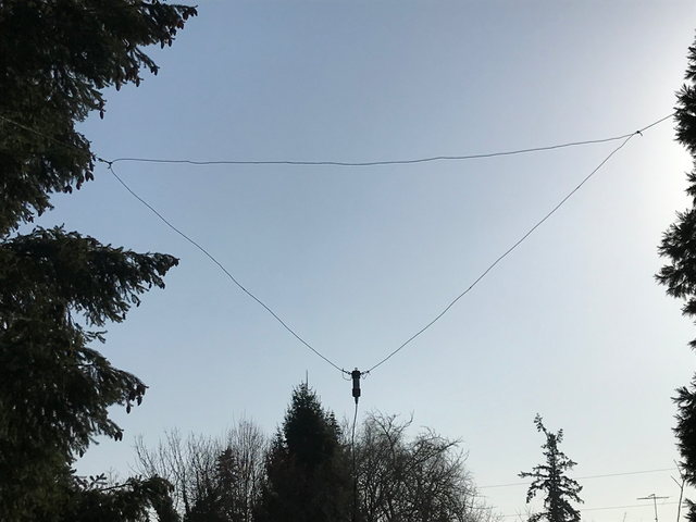
It is a delta loop with the point down, as described in the Full Wave Loop Theory article. Nominal dimensions are provided on the Loop Dimensions page, with construction tips on the Loop Construction page.
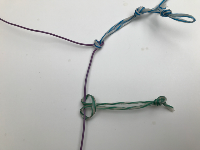
I start with the nominal dimensions and tie a small loop in each corner of the wire to attach the ropes. Then when I roll it up, I know right where to tie them next time.
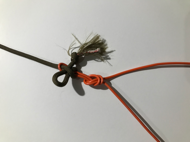
If I think I’m going to have to make a lot of adjustments, I use a simpler method of tying that makes it easier to adjust, but I would generally still tie the loops once know where they go.
I actually have two of these antennas. One uses a commercial 4 : 1 balun, and the other is fed with a quarter wave of US “Zip Cord” (lightweight 2-conductor power cord). The wire is insulated 1 mm (AWG #18), and the two have been installed at different heights above ground. Comparing the actual measured dimensions with the nominal ones may give us some idea of the expected variations.
The one with a balun has a total wire length of 42.4 m (139 feet), 16.6 m (54.5 feet) wide, and 12.9 m (42.25 feet) for the side length. Calculated height is 9.8 m (32.3 feet). The top of the loop was installed at about 12 m (40 feet), so the bottom end was about 2m (6 feet) off the ground, which probably accounts for much of the difference from the nominal values (although the use of insulated wire will also affect things).
The second loop is designed for a slightly higher impedance (220 – 240 ohms), as the impedance of the zip cord is typically around 105 – 110 ohms (it varies with wire size and manufacturing tolerances). The actual dimensions for 1 mm (AWG #18) insulated wire are a total wire length of 43.9 m ( 144 feet ), width of 16.5 m (54 feet), side length of 13.7 m (45 feet), and calculated height of 11 m (36 feet). This loop is typically installed around 18 m (60 feet) above ground, which raises the natural feedpoint impedance, requiring the width to be slightly less than the the other loop even though it is designed for a high impedance. The quarter wave matching section is 6.1 m (20 feet) long, with the bottom of the zip cord wrapped through a pair of #43 ferrite cores to serve as a balun. That puts the bottom of the matching section less than 2 m (6 feet) from the ground.
Both loops were adjusted by first trimming the wire length to center the SWR curve in the band, then moving the corner ties for minimum SWR. Both have an SWR under 1.35 : 1 from 7.0 to 7.3 MHz. In practice, variations in hanging the loop generally don’t raise the SWR above 1.5 : 1, so I haven’t worried about further adjustments.
Clearly this can be built for other bands. It is particularly useful for working the entire width of the 10m band.
A 100 ohm feedline for matching can be made with two parallel lengths of 50 ohm coax (use the two center conductors as a balanced line, and tie the shields together at each end), or, for a light weight antenna, a twisted pair from a CAT5 or similar computer network cable has a 100 ohm impedance. While the zip cord is close to 100 ohms, typical speaker cables with smaller wires tend to have impedances around 130 to 150 ohms, requiring a feedpoint impedance in the 330 – 450 ohm range, which is generally beyond the available range when the antenna is stretched out as wide as it will go.
The commercial 4 : 1 balun I use is an older voltage balun design, and 40m appears to be the band where it gives the lowest SWR when terminated with a 200 ohm resistor. Fortunately there is enough range of adjustment in most loops to correct for some flaws in the balun. A standard 4 : 1 balun using 1/2 wave of 50 ohm coax (often used on VHF and UHF beams) can also be used, if the added coax weight isn’t a problem.
Overall the Field Day team has been very happy with these antennas. Well, once they are up, some operators don’t actually notice them at all, because the SWR is always low, and the antennas make lots of contacts. (One is installed over sloping ground, which helps to lower the take-off angle.) But that is the type of antenna that I want for Field Day!