Understanding the Quarter-Wave Ground Plane Antenna
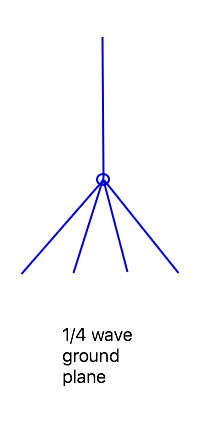
The Quarter Wave Ground Plane is a very common, simple, and effective antenna. Generally it consists of a quarter wave vertical radiator connected to the center of the coax feeder, and 4 radials, often sloping downwards, that are also about a quarter wave long. They are easy to build, often using a chassis-mount coax connector.
Unfortunately, the traditional ham radio folklore explanation of a quarter wave ground plane antenna is rather flawed. For example, I recently came across yet another web site that gave the following properties:
- It has little or no gain – less than that of a dipole.
- A 5/8 wave vertical is much better.
- The radiator is given by the standard formula of 71.5 / F (MHz) meters or 234 / F (MHz) feet. The radials are 5% to 10% longer to act as a reflector.
None of these are necessarily true!
Let’s look at the source of these myths…
history
A vertical radiator, fed against “ground” of some sort, has been a common antenna design since the early days of radio. As operations moved to higher frequencies, and steel towers became more available, it was more practical to make the antenna 1/4 wave tall, even at MF, eliminating the need for a loading inductance (required for shorter antennas).
In 1924, S. Ballantine analyzed different lengths of vertical radiators with the feedpoint at the base, over infinite, perfectly conducting ground. Based on the combination of the direct and reflected waves, he showed that a quarter wave radiator was about 1.5 dB below a 1/2 wave radiator, and 3 dB down from a 5/8 wave vertical. As I discuss in the article on 5/8 wave verticals, these numbers have since been used in many situations where the original conditions don’t apply.
Generally, as hams we don’t have an infinite, perfectly conducting ground (although a boat in salt water can come close). Particularly on the higher frequencies, we also aren’t limited to placing the feedpoint at ground level. In fact, when we use the term “ground plane antenna”, we usually mean one that is elevated, and fed against a set of radials rather than an actual earth ground.
How does this affect the antenna behavior? Let’s look at each condition…
infinite ground plane
We still (usually) have a near-infinite ground plane, called the Earth, under the antenna, and the reflections from this will affect the radiation pattern in the same way that Ballantine calculated nearly a century ago. But the reflection is from the Earth, not from the ground plane radials (especially when they are sloping). When the antenna is mounted over a large flat metal object, such as the roof of a car, there may be reflections from both objects, depending on the vertical angle, that both affect the vertical pattern.
Apparently, the reason for making making the ground radials 5% to 10% longer than the top radiator was the mistaken idea that the radials were reflecting the signal, so should be made longer by the same ratio as the reflector in a yagi antenna. In fact, the radials are driven with RF from the feedline, just like the rest of the antenna.
perfectly conducting ground plane
For a ground-mounted antenna, real ground introduces a couple of extra factors into the equation. First, there is ground loss resistance, due to RF flowing through the dirt. This tends to reduce signals more for quarter wave (and shorter) antennas more than for longer ones with a higher feedpoint impedance, due to higher currents through the loss resistance.
The other change in the radation pattern is due to the phase shift in the reflection coefficient at low angles. Rather than the reflection being in phase with the incident wave, so the reflection adds to the transmitted signal, it becomes more out of phase, resulting in relative nulls in the radiation pattern at low angles. (This is true of any vertically polarized antenna.)
feedpoint at ground level
The reason for gain differences cited in Ballantine’s article were due to the differences in the height above ground of the current maxima of the antenna, and the resulting effects of the ground reflections. When we raise the feedpoints of the antennas above ground, and put the current maxima at the same height, we discover that there is virtually no significant difference in gain among the three antennas. Certainly at VHF, we rarely would use such an antenna with the bottom at ground level. Once elevated, a quarter wave ground plane works as well as a vertical dipole or other half wave antenna, and often is easier to feed for vertical polarization.
And, if we look at carefully at the antenna, we can see why it is about the same as a dipole: because it is essentially a vertical dipole, with the bottom conductor split into multiple parallel wires and spread apart to form the ground radials.
current distribution on antenna
Plotting the current distribution on the antenna is pretty straightforward.
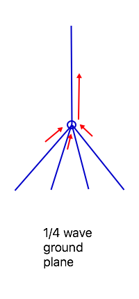
Current is maximum at the feedpoint, and flows in the same direction in each of the radials. The horizontal components of the currents on the radials cancel each other, but the vertical components add in phase with the radiator.
When the radials are vertical, we have a vertical dipole. When the radials are horizontal, they do not contribute to the radiation: this lowers the feedpoint impedance. Sloping the radials down at about 45 degrees to vertical gives a feedpoint impedance close to 50 ohms, suitable for direct coax feed.
In practice, while 4 radials are common, 2 or 3 will work nearly as well, although the dimensions may change slightly. The 2-radial version is convenient to fit in a flat space, such as against a window.
detailed analysis
Let’s begin by looking at the behavior of a ground plane antenna with equal lengths of vertical and 4 radials. I’ve chosen 2.5 m ( 8.2 ft ) of 4mm ( 5/32 inch ) rod for the elements here, which resonates at 28.5 MHz when the radials slope down at 45 degrees from vertical. We can observe the changes in gain, feedpoint impedance, and resonant frequency as the radials are tilted downwards from 0 degrees (horizontal) to 80 degrees, or almost vertical. (90 degrees would be a vertical dipole.)
| angle | resonant frequency MHz | impedance ohms | gain dBi |
|---|---|---|---|
| 0 | 29.8 | 23 | 1.4 |
| 10 | 29.5 | 29 | 1.5 |
| 20 | 29.2 | 36 | 1.6 |
| 30 | 28.9 | 42 | 1.8 |
| 40 | 28.6 | 47 | 2.1 |
| 50 | 28.3 | 52 | 2.3 |
| 60 | 28.1 | 55 | 2.6 |
| 70 | 27.8 | 56 | 2.9 |
| 80 | 27.6 | 55 | 3.2 |
The first thing to notice is that the resonant frequency shifted, even though the antenna elements were the same length for each case. This should be a warning that any simple formula for the element length is not going to be correct, unless it specifies the radial angle (as well as the element diameter).
Meanwhile, notice that with 30 degrees or more of slope, the antenna is a good match to 50 ohm coax, and that fine adjustment can be made just by bending the radials up or down.
The gain values actually vary more than I expected – there may be an issue with my model with the overlap of the radials as the angle between them decreases that I need to look into. But given that a dipole is theoretically 2.15 dBi, we see that the values are actually pretty close, especially when the radials are sloping. Basically, a ground plane with sloping radials is equivalent to a vertical dipole or other half-wave antenna in terms of performance. It often is easier to feed from the bottom.
dimensions
The original dimensions used quarter wave radiator and radials. Later the radials were lengthened due to the incorrect assumption that would optimize them to act as reflectors. But is there a “correct” set of dimensions?
Some years ago, Woody Smith W6BCX (inventor of the half square and bobtail curtain, among other antennas) wrote an article in QST magazine where he shortened the radiator and lengthened the radials to decrease the common mode current on the feedline. At the time I was building 2m ground plane antennas using a 49.5 cm (19 1/2 inch) radiator and radials. This posed a problem (for those of us who want to optimize our use of materials) because the brass brazing rod I was using for the vertical portion was sold in 91.4 cm (36 inch) lengths, which left a lot of material wasted. Now I could shorten the vertical part to 45.7 cm (18 inches) and get two from a single length of rod. For this to work, the radials needed to be extended to 61 cm (24 inches). I’ve never actually tested to see whether this reduces common mode current (that will be a later project), but that is how I build all my 2m ground planes now. Of course, it isn’t a problem if your brazing rod comes in 1m lengths!
That suggests, however, that the length of the vertical portion isn’t critical, as long as the radial lengths are adjusted for resonance. So I collected some data, changing the vertical portion of the previous 10m model from 2m to 4m (and readjusting the radials for resonance at 28.5 MHz when sloping downwards at 45 degrees).
| vertical length cm | vertical length (inches) | radial length cm | radial length (inches) | impedance ohms | gain dBi | SWR BW 1.5 : 1 MHz |
|---|---|---|---|---|---|---|
| 200 | ( 79 ) | 445 | ( 175 ) | 125 | 1.8 | 2.5 |
| 225 | ( 89 ) | 350 | ( 138 ) | 70 | 2.1 | 2.0 |
| 250 | ( 98 ) | 250 | ( 98 ) | 50 | 2.2 | 1.5 |
| 275 | ( 108 ) | 173 | ( 68 ) | 44 | 2.2 | 1.3 |
| 300 | ( 118 ) | 122 | ( 48 ) | 45 | 2.2 | 1.2 |
| 325 | ( 128 ) | 90 | ( 35 ) | 52 | 2.2 | 1.2 |
| 350 | ( 138 ) | 67 | ( 26 ) | 64 | 2.2 | 1.2 |
| 375 | ( 148 ) | 51 | ( 20 ) | 84 | 2.3 | 1.2 |
| 400 | ( 157 ) | 38 | ( 15 ) | 120 | 2.3 | 1.2 |
The first thing to notice is that the impedance and gain are relatively constant, and a good match for coax cable, between about 225 cm and 375 cm. The impedance can be adjusted by changing the slope angle of the radials if needed. This is a versatile antenna with regards to dimensions, as long a the other parts are adjusted to compensate.
A corollary of this is that the antenna can be tuned by adjusting the length of either the vertical part or the radials. Sometimes one may be more convenient than the other.
The next important finding is that the required radial length for resonance varies faster than the vertical length, at least in the nominal 1/4 wavelength range. This shouldn’t be too surprising: in this range the reactance change with length is relatively constant. However, with 4 radials connected in parallel, the total change in reactance will be only 1/4 of the shift for each individual radial (in the same way that 4 resistors in parallel will have 1/4 the resistance of a single resistor). So the radials need to be lengthened (or shortened) by roughly 4 times the change to the vertical element.
For the mistaken guidance to make the radials 5% to 10% longer to act as a reflector, it will shift the resonant frequency by 2.5% or less, which is easily corrected for in normal tuning. It doesn’t hurt the end result, even though the reasoning is wrong.
Consider now the bottom entry in the table: the radials are less than 10% the length of the vertical element, which is about 80% of a nominal half wavelength. This will look more like a vertical fed off-center, with a little bit of “capacity hat” on the bottom – which, in fact, is what it is. There is no discrete point where an antenna changes from one type to another: they are related types, and either description still applies.
The last column gives us a clue that the radials act as a “fat element” and increase the SWR bandwidth of the antenna, at least when they are close to 1/4 wavelength. As they get shorter, this effect disappears.
number of radials
I said previously that 2 or 3 radials will work as well as 4. Let’s repeat the prior analysis with different numbers of legs. First, using 3 radials:
| vertical length cm | vertical length (inches) | radial length cm | radial length (inches) | impedance ohms | gain dBi | SWR BW 1.5 : 1 MHz |
|---|---|---|---|---|---|---|
| 200 | ( 79 ) | 396 | ( 156 ) | 94 | 1.8 | 2.0 |
| 225 | ( 89 ) | 328 | ( 129 ) | 64 | 1.9 | 1.7 |
| 250 | ( 98 ) | 255 | ( 100 ) | 51 | 2.1 | 1.4 |
| 275 | ( 108 ) | 189 | ( 74 ) | 46 | 2.1 | 1.3 |
| 300 | ( 118 ) | 138 | ( 54 ) | 47 | 2.2 | 1.2 |
| 325 | ( 128 ) | 102 | ( 40 ) | 54 | 2.2 | 1.2 |
| 350 | ( 138 ) | 76 | ( 30 ) | 66 | 2.2 | 1.2 |
| 375 | ( 148 ) | 57 | ( 22 ) | 86 | 2.2 | 1.2 |
| 400 | ( 157 ) | 42 | ( 17 ) | 120 | 2.2 | 1.2 |
Then, with just 2 radials:
| vertical length cm | vertical length (inches) | radial length cm | radial length (inches) | impedance ohms | gain dBi | SWR BW 1.5 : 1 MHz |
|---|---|---|---|---|---|---|
| 200 | ( 79 ) | 356 | ( 140) | 72 | 1.6 | 1.5 |
| 225 | ( 89 ) | 309 | ( 122 ) | 59 | 1.8 | 1.4 |
| 250 | ( 98 ) | 259 | ( 102 ) | 53 | 1.9 | 1.3 |
| 275 | ( 108 ) | 211 | ( 83 ) | 51 | 2.0 | 1.2 |
| 300 | ( 118 ) | 168 | ( 66 ) | 54 | 2.0 | 1.2 |
| 325 | ( 128 ) | 132 | ( 52 ) | 61 | 2.0 | 1.2 |
| 350 | ( 138 ) | 103 | ( 41 ) | 74 | 2.1 | 1.2 |
| 375 | ( 148 ) | 80 | ( 31 ) | 95 | 2.1 | 1.2 |
| 400 | ( 157 ) | 60 | ( 24 ) | 131 | 2.1 | 1.2 |
The SWR bandwidth is less with fewer radials, and the radial lengths don’t shift as much (which we expected based on our explanation of the change in reactance) but otherwise performance is pretty similar. The pattern becomes somewhat less circular with just 2 radials, but the difference is less than 1 dB or so (I’ve averaged the gain minimum and maximum in the table) so it will be insignificant in practice.
summary
We have seen that the ground plane antenna works about as well as a vertical dipole, the dimensions can be adjusted as needed to make use of available materials, and the angle of the radials can be used to set the feedpoint impedance. It is often easier to use than a dipole when it needs to be fed at the bottom, as there is less interaction between the antenna and the outside of the feedline, and no special matching circuit is needed.
Now, the next step is to build one!