Building a Simple Ground Plane antenna
introduction

A ground plane antenna for 2m or 70cm is one of the simplest antennas to build and get working, and it can work quite well for repeater or simplex operation. It is easy to build for other bands as well.
I’ll show you several different construction methods that you can use, based on the materials you have available.
They are easy to adjust for low SWR, often just by bending the wires up or down, and cover a wide bandwidth.
Most of the ones you see in photos are ones that I use for temporary or portable operation, so they aren’t built to be rugged. However, they are cheap antennas, so I make several at a time and keep spares on hand. That also means they are expendable – I can use them for emergencies or give one to a new ham without worrying if I will get it back.
dimensions
In the article on Understanding a Ground Plane, we showed that many different sets of dimensions can be used, depending on the length of the vertical part and the number of radials. But let’s start with some common dimensions where the vertical portion and the radials are the same length. We’ll add an extra 2m design for the Americans who get their brass brazing rod in 91.44 cm (36 inch) lengths. These dimensions are for 3 mm (AWG #8 or 1/8 inch) wire: fatter wire will require slightly shorter elements. They will serve as a starting point: the SWR bandwidth is typically wide enough that they shouldn’t require a lot of adjustment within a band.
| center frequency MHz | vertical length cm | radial length cm | vertical length (inches) | radial length (inches) | number of radials | 1.5 : 1 SWR bandwidth | 2 : 1 SWR bandwidth |
|---|---|---|---|---|---|---|---|
| 28.5 | 250 | 250 | ( 98.5 ) | ( 98.5 ) | 4 | 1.5 MHz | 2.5 MHz |
| 52 | 136.5 | 136.5 | ( 53.75 ) | ( 53.75 ) | 4 | 2.9 MHz | 5.1 MHz |
| 70.4 | 100.5 | 100.5 | ( 39.5 ) | ( 39.5 ) | 4 | 4.2 MHz | 7 MHz |
| 145 | 48.3 | 48.3 | ( 19 ) | ( 19 ) | 4 | 10 MHz | 17 MHz |
| 146.5 | 45.7 | 58.4 | ( 18 ) | ( 23 ) | 4 | 10 MHz | 17 MHz |
| 223 | 31.0 | 31.0 | ( 12.25 ) | ( 12.25 ) | 4 | 17 MHz | 30 MHz |
| 440 | 15.4 | 15.4 | ( 6 ) | ( 6 ) | 4 | 40 MHz | 68 MHz |
Dimensions will be similar with fewer radials, although they might need to be slightly longer. The angle of the radials sets the feedpoint impedance, and around 45 degrees is typical in many cases.
Radial lengths for vertical elements that are up to 10% shorter than those listed can be estimated by adding a correction factor of the difference in vertical length times the number of radials. So, if the vertical portion is shortened by 1 cm, the radials would be lengthened by 4 cm for 4 radials, or 2 cm for 2 radials. This formula will result in radials that are too short when the vertical is lengthened, and the radials may only need to be shortened by half the calculated amount.
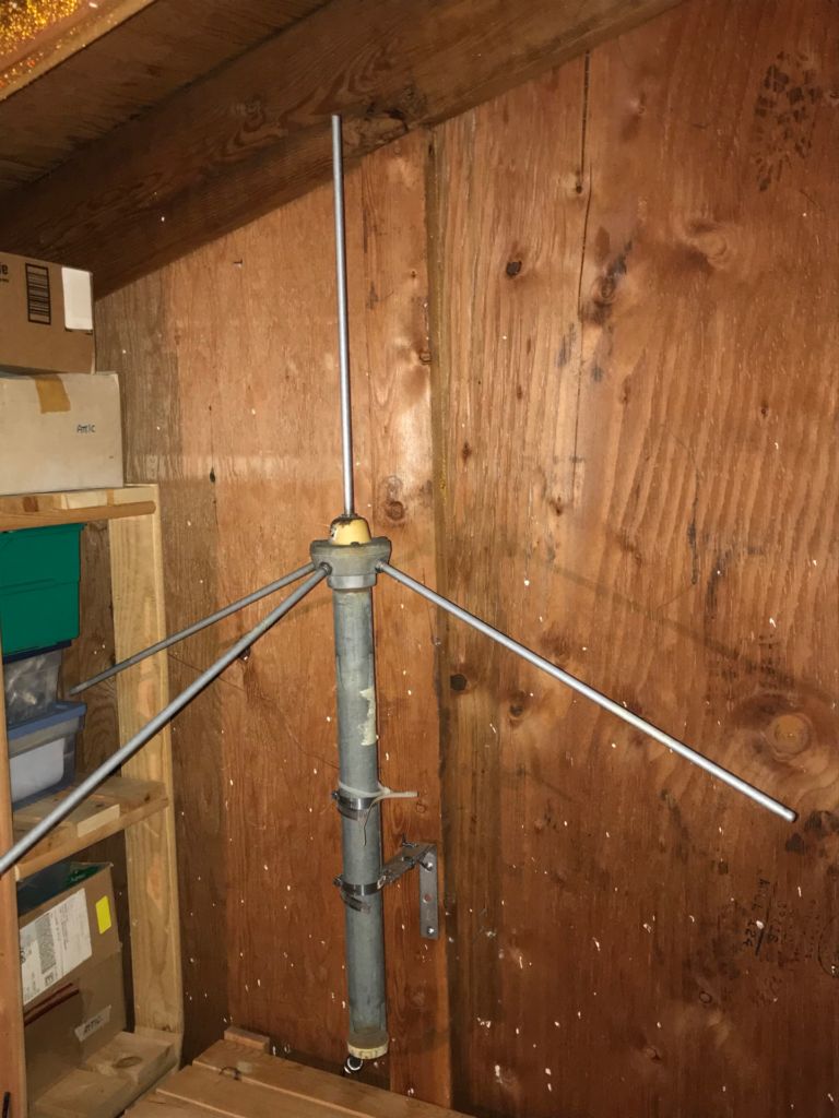
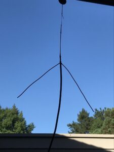
Why would we use something other than 4 radials? Ground plane antennas designed for 11m “Citizens Band” operation often use 3 radials to save the cost of materials. I have a heavy-duty commercial VHF ground plane where one radial was broken off: I mount the flat side against the wall in my attic, and it works quite well, even though the radials are not symmetric. For hanging an antenna against window, the use of just 2 radials allows it to fit flat behind a curtain. The original ground plane antenna, in fact, used just two radials, and it may be more convenient for portable wire versions at HF. There is little practical difference among them.
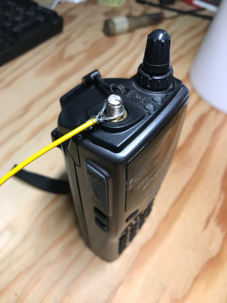
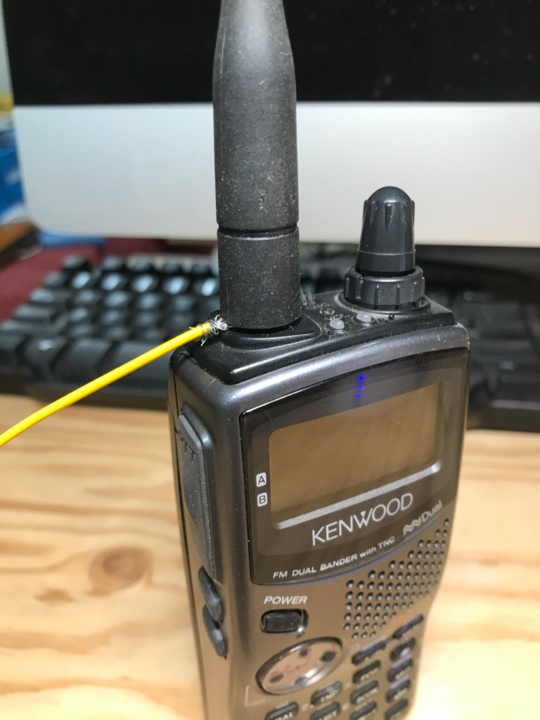
What about only using one radial? Sure, that works, too – it just becomes a dipole. One problem, however, is that with a straight vertical dipole there is more coupling to the coax. However, a single sloping radial will still function, although the pattern might not be perfectly circular. A common use of this technique is to add a flexible wire radial hanging from the antenna connector on VHF/UHF HT, working in conjunction with the antenna normally connected to the radio. This can provide a significant improvement in signal, as it provides a larger ground plane compared to the circuitry inside the radio.
materials
The common lightweight construction for VHF/UHF uses a chassis-mount coax connector as a base, with solid wire elements, often around 2mm (AWG #12). Brass brazing rod works well for the vertical part, as it tends to be stiffer than wire. Avoid using copper-plated steel welding rods, however, as the copper coating is very thin and weathers off quickly, and the underlying steel can be lossy. Tubing or flat straps can also be used for the elements.
When the antenna is hanging from the vertical element, it can use light wire for the vertical part, and the radials can also be flexible wire if they are tied off with ropes, which makes an effective HF antenna hanging from a single support.
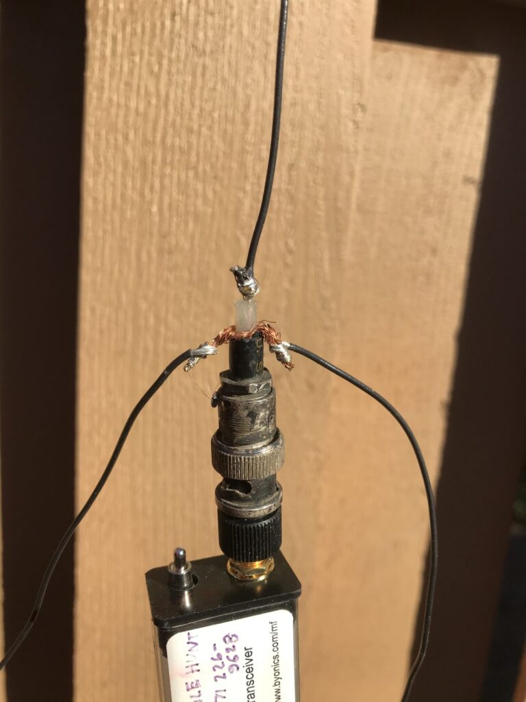
Of course, the antenna doesn’t need to use a coax connector. The 2-radial UHF ground plane shown above uses an extended center conductor of the coax for the vertical portion, and a single bent wire soldered to the coax shield for the radials.
construction
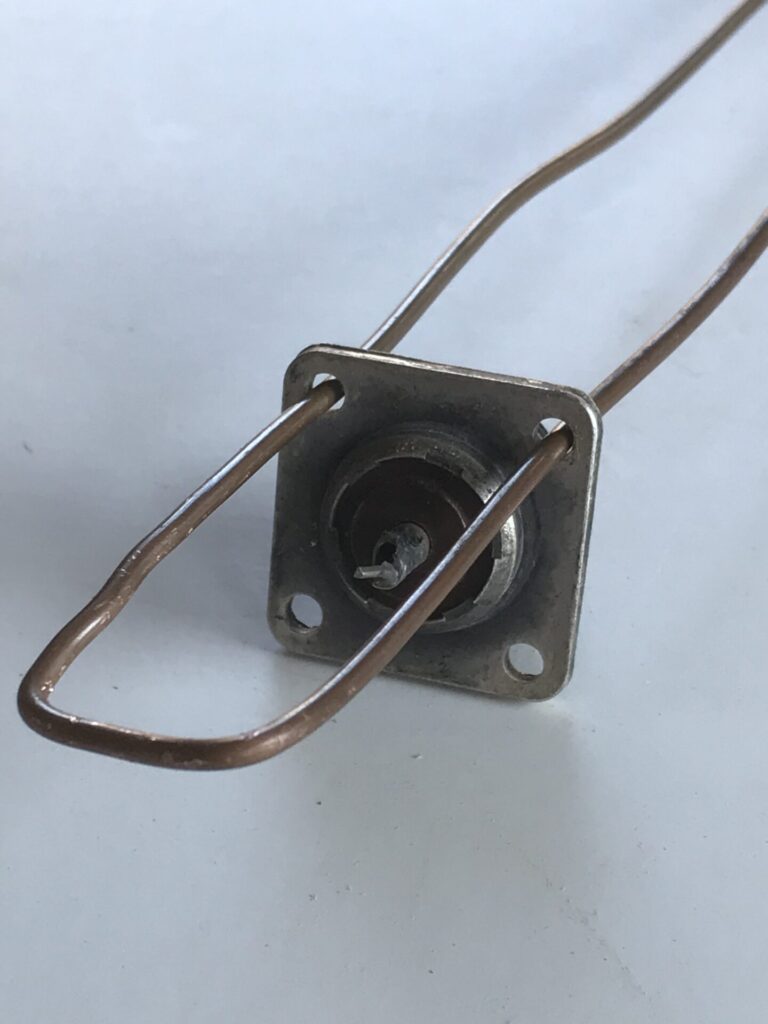
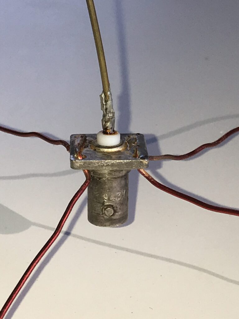
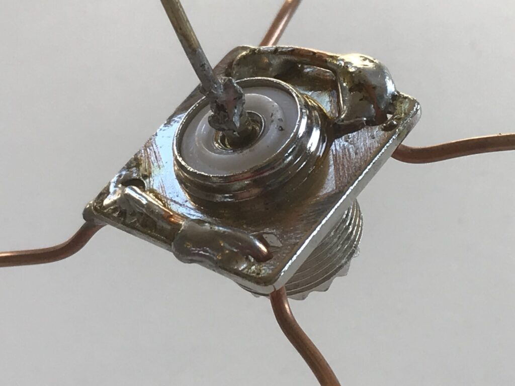
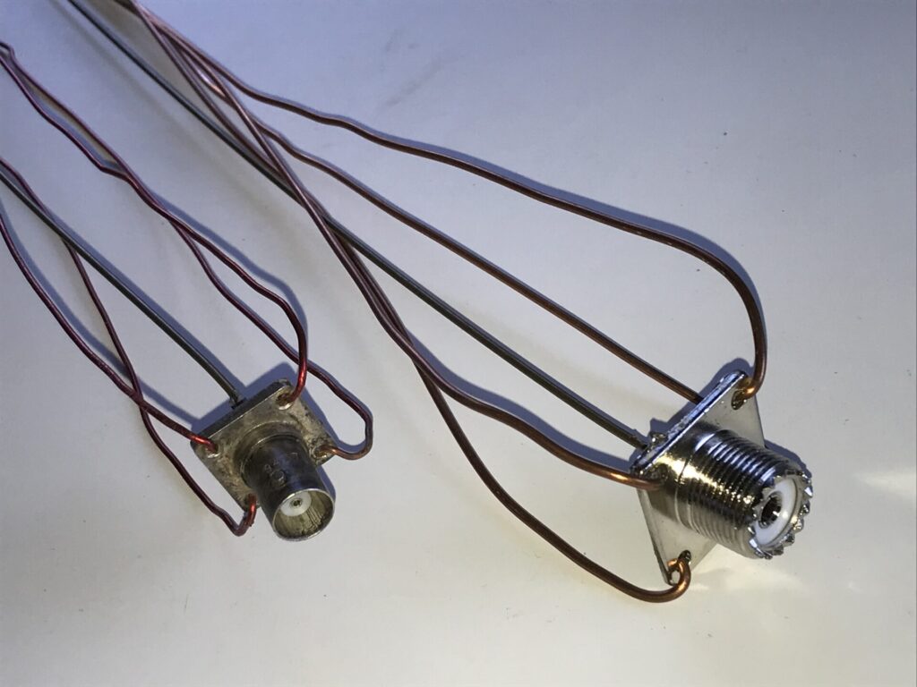
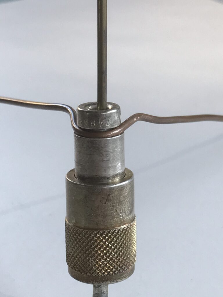
The common construction using a coax connector is fairly straight-forward. The mounting holes on a standard SO-238 socket are about 3.2mm ( 1/8 inch ). My usual approach is to cut a single piece of wire slightly longer than needed for 2 radials, bend it in a narrow “U” shape, and pass it through two adjacent holes. The center section is then soldered to the socket flange, providing a more durable connection than trying to solder separate wires into each hole. This takes a relatively large soldering iron. I have found it is easiest to trim the radials to length after the wire is soldered.
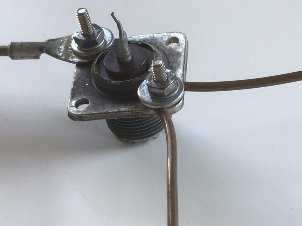
There are several other constructions, often attaching the radials with bolts. The standard holes should take a 3mm ( SAE #4 ) machine screw, or they can be drilled and tapped for a larger size.
The radials can be secured under a bolt, nut, and washer, or attached with a lug. In practice, I have found that lugs tend to be a weak point that can flex and break.
The center element can just be soldered directly to the center conductor of the socket. If it is too large to fit, then a small sleeve of brass tubing or similar can be slipped over the center pin and the element soldered to that.
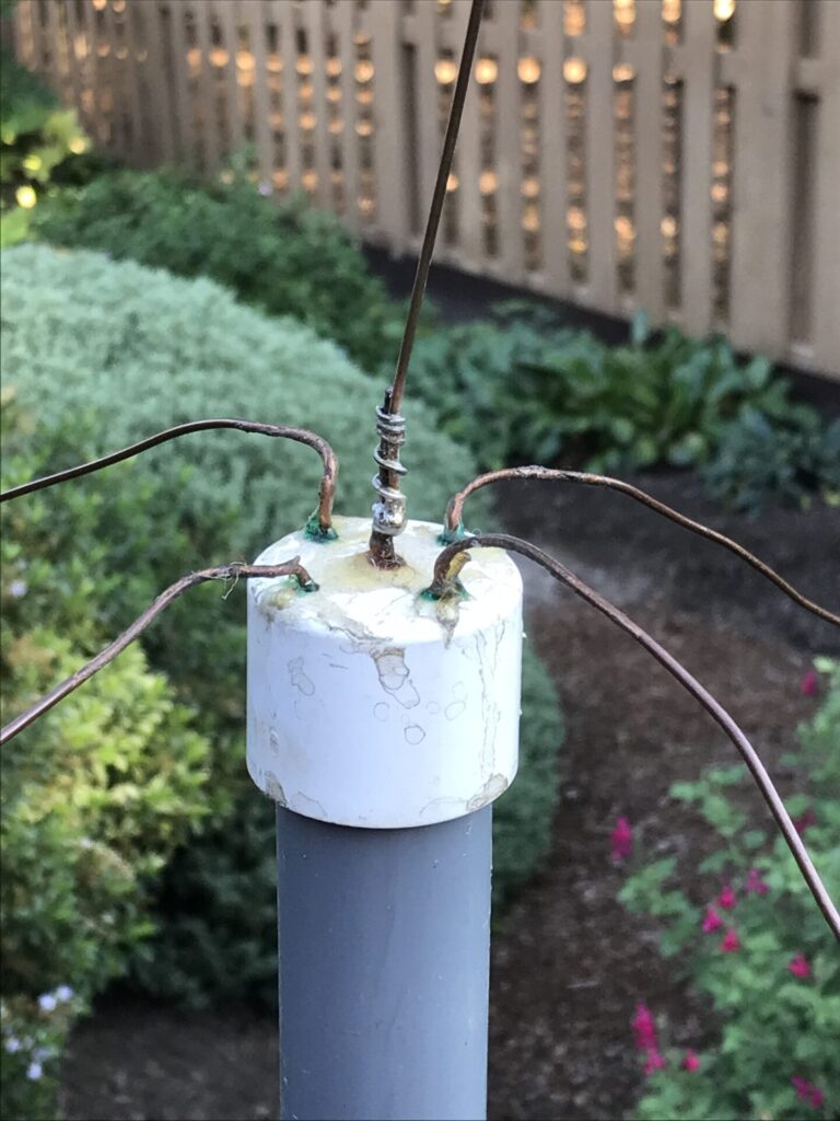
A plastic pipe cap or other cover can be used to protect the feedpoint from rain, with the radials coming the bottom, sides, or top, whichever is easiest.
Wire radials can be folded up against the vertical element for storage or transport. They do weaken and break eventually from repeated bending, but many of mine have lasted 10 to 20 years of occasional use.
In the November 2011 issue of QST magazine, Pedro Motilla EA5BFT introduced a new method of assembly that doesn’t require soldering, and permits the elements to be removed for storage. This makes use of the metal connector pieces inside junction blocks.
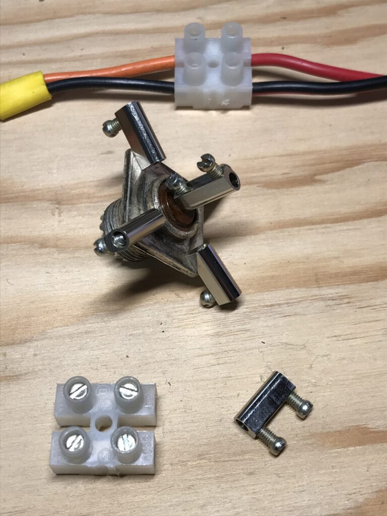
The metal pieces are easy to remove by unscrewing the clamp screws, then using a sharp knife to cut off one end of the housing, or slitting the bottom on each side of the metal. One screw is passed though a hole in the coax socket for each radial, and another slipped over the center pin and the screw tightened to hold it in place. Then the elements are inserted into the open ends and the screw tightened to hold them.
I have not yet built any ground plane antennas this way, but it looks like an excellent approach, and makes it easier to replace broken elements, without requiring any soldering.
There are other methods besides using a chassis-mount coax socket. The elements can be attached to coax plugs, or soldered directly to the wire elements (particularly for hanging antennas).
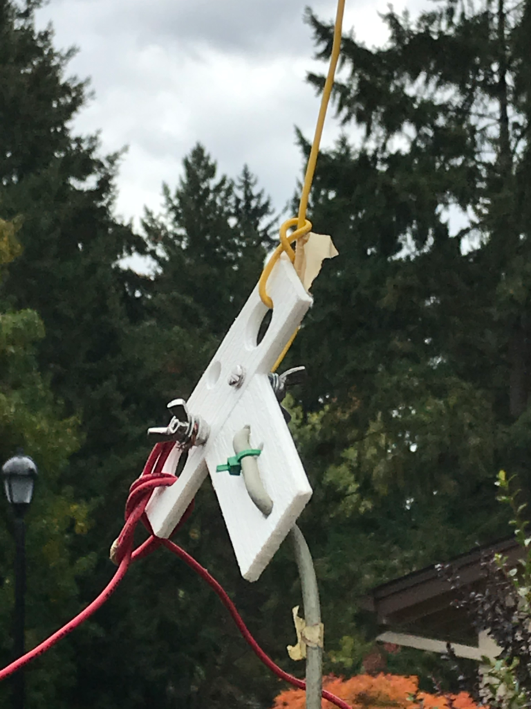
For HF wire ground planes, any sort of center insulator can be used, basically forming a dipole with one vertical wire and two or more wires connected to the other side. For temporary antennas the wires can be attached directly to the coax, as shown previously. Here is an example of a wire HF ground plane antenna feedpoint using my portable dipole kit: the two red radials are the wires for a 20m dipole, and the yellow vertical wire is an additional piece cut to about the same length.
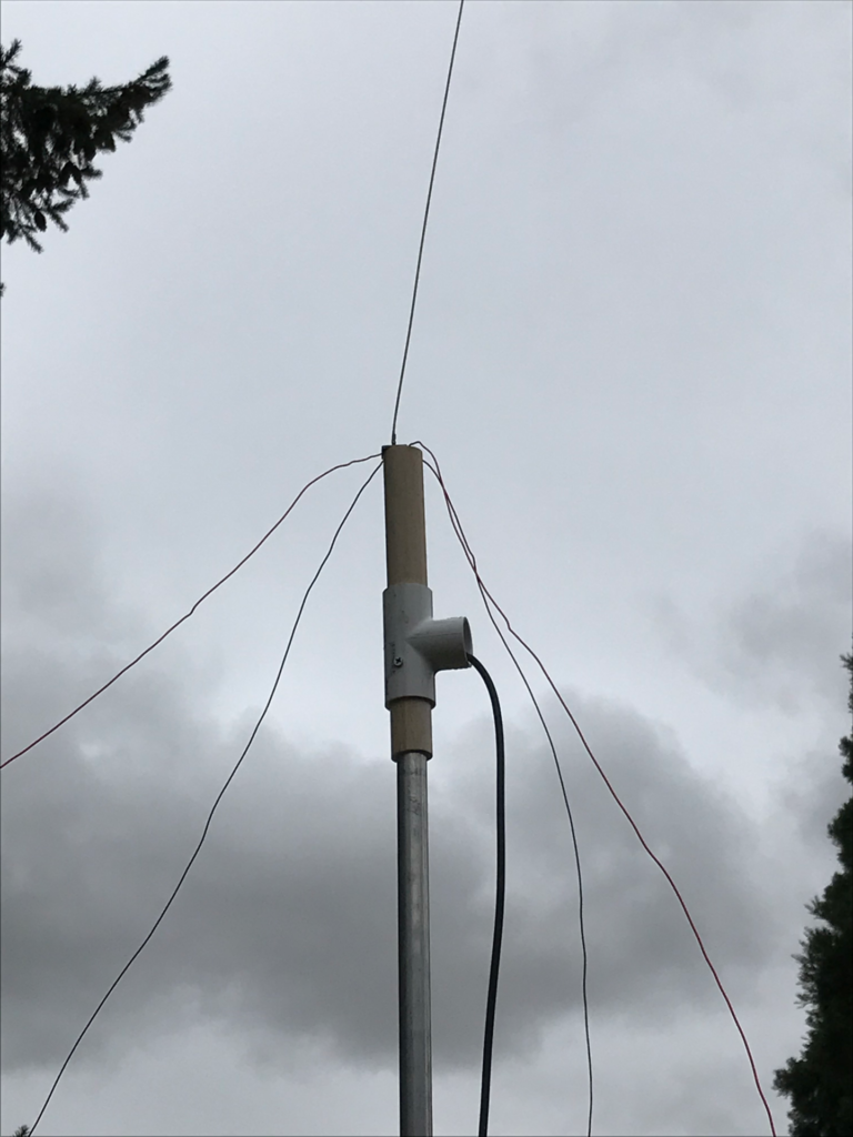
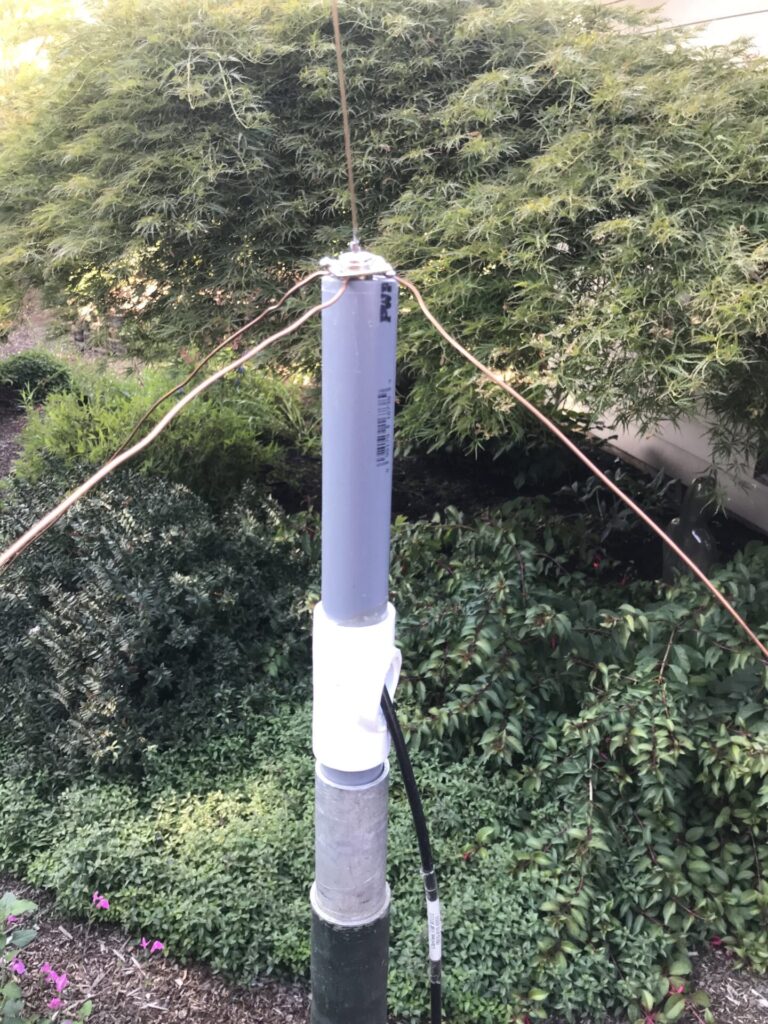
For ground plane antennas made using rigid aluminum or copper tubing, the vertical portion can be mounted by sliding the tubing over an insulated rod, or putting an insulated tubing or pipe beween it and the mounting brackets. Various sorts of plastic or metal brackets are sold for pipe and electrical conduit that can be used. Mechanical strength of the joint is important, especially as the vertical element is made longer.
tuning
If the SWR curve is too far off from the desired frequency, the length of either the vertical portion or the radials (or both) can be adjusted as needed to center it as desired. The slope of the radials can then be varied to improve the match. In many cases, due to the wide bandwidth, no adjustment may be needed.
mounting
For temporary use, mounting the antenna in the end of a short length of pipe is often sufficient, with the weight of the coax holding it in place. If you use bolts to connect the radials, a metal bracket can be secured under one of them for mounting. The commercial antenna mounted in the attic uses two standard “L” brackets bolted together to make a “Z” shape, with one end screwed to the wall and the other attached to the antenna with hose clamps.
Wire antennas can be hung from a rope, often a halyard passing over a tree branch. I also hang some using wire hooks tied to the top of the vertical element with a short length of rope: these can then be hooked over a tree branch using a tall pole.
common mode current
While the spacing of the radials on a ground plane reduces the common mode current on the feedline compared to a coaxial or sleeve dipole, decoupling isn’t perfect. Many commercial installations use some additional decoupling to prevent the current on the feedline from affecting the radiation pattern. One common solution is to add a second set of radials 1/4 wavelength below the first: often the lower set has 5 radials compared to 4 in the upper set. They may also be mounted on a 1/4 wave sleeve that is grounded to the mast at the bottom. A feedline choke may help, especially with a second one 1/4 further down the cable.
In practice, these antennas have proven effective without such additional measures, but, as is often the case with common mode current, details will depend on the specific installation, grounding, coax length, etc. Users should be alert for such problems: if the antenna doesn’t provide the expected coverage, then some additional measures may be needed.