Understanding the 5/8 wave antenna
last updated 28 November 2023.
One of the problems we often run into when trying to understand antennas is when a condition that applies in very specific cases gets generalized and accepted as “fact”, even in situations where it doesn’t apply. A classic example of this is the 5/8 wave vertical antenna.
history
In December 1924, S. Ballantine introduced the 5/8 wave vertical in a paper titled, “On the Optimum Transmitting Wave Length for a Vertical Antenna over Perfect Earth”. He showed that, for a broadcast antenna over perfect earth, with the feedpoint at ground level, and assuming sinusoidal current distribution, ground wave radiation was maximum for an antenna length of about 225 degrees, or 5/8 wavelength.
Let’s compare the radiation patterns of several possible vertical antenna lengths in this situation:
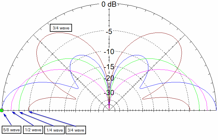
We can see that as the antenna is lengthened beyond 1/4 wavelength, the radiation pattern is flatter to the ground, putting more signal into ground wave (that is, horizontally along the bottom of the plot). In accordance with the “conventional wisdom”, the 5/8 wave antenna has about 3 dB gain over a 1/4 wave antenna, although we can see the high angle lobes starting to form in the pattern of the taller antenna. Lengthening the antenna further to 3/4 wavelength puts less radiation at the horizon and more into the high angle lobes. Which antenna works “better” for a particular path, of course, depends on the required vertical angle of radiation, but for MW broadcast applications, ground wave radiation is the major coverage mode, and optimization at 0 degrees is a good measure.
By putting the numbers for low radiation angles in to a table, it is easier to see the differences. The 1/2 wave radiator is about the same as a 5/8 wave at around 15 degrees, and at 25 degrees the quarter wave radiator takes the edge. The 3/4 wave antenna shows a null at about 20 degrees, with maximum radiation close to 45 degrees above the horizon.
| elevation angle degrees | 1/4 wave dBi | 1/2 wave dBi | 5/8 wave dBi | 3/4 wave dBi |
|---|---|---|---|---|
| 0 | 5.2 | 6.6 | 8.0 | 3.2 |
| 5 | 5.1 | 6.5 | 7.8 | 2.5 |
| 10 | 5.0 | 6.1 | 6.9 | 0.1 |
| 15 | 4.7 | 5.5 | 5.4 | -5.1 |
| 20 | 4.4 | 4.7 | 3.2 | -10.5 |
And so we have developed the “conventional wisdom” for nearly a century that the 5/8 wave is the optimum length for a vertical antenna, and it has 3 dB of gain over a quarter wave ground plane.
usage by broadcast stations
Does this mean that the 5/8 wave vertical is the standard antenna for medium wave broadcast stations? No. Or at least, only rarely, since about 1934. It turns out that the high angle radiation increases fading, which limits the acceptable distance for broadcast reception. Instead, a length of 0.528 wavelengths is used as an “anti-fading antenna” for high power stations. At lower power levels, where the ground wave attenuation limited the coverage before the fading zone was reached, the taller antennas didn’t add significant coverage distance for the increased cost, and often towers as short as 1/6 wavelength are used instead. (5/8 wave radiators may still be useful over salt water, where ground wave attenuation is much less, and fading isn’t as much of a problem.)
over real ground
In the real world, many of us don’t live over perfect ground, or even over salt water (which comes close). I ran the same models over the typical soil in my area:
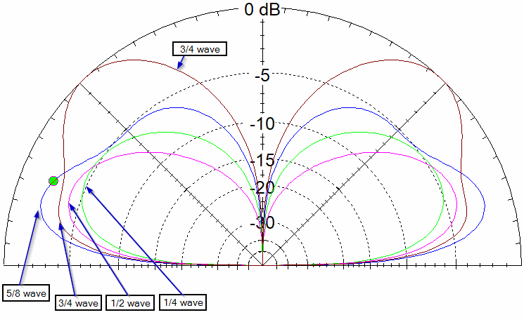
The first thing to notice is that the 3/4 wave antenna is now better than the 1/4 or 1/2 wave antennas at all radiation angles! And maximum radiation is no longer at horizon, but somewhat above it.
We can extract more detail from a table of readings at low elevation angles:
| elevation angle degrees | 1/4 wave dBi | 1/2 wave dBi | 5/8 wave dBi | 3/4 wave dBi |
|---|---|---|---|---|
| 5 | -7.5 | -5.5 | -2.5 | -3.7 |
| 10 | -3.5 | -1.7 | 1.1 | -0.2 |
| 15 | -1.7 | -0.2 | 2.2 | 0.7 |
| 20 | -0.9 | 0.2 | 2.1 | 1.0 |
The 5/8 wave antenna now has a 5 dB advantage over the 1/4 wave antenna, at least at some heights. However, also notice that the calculated signal strengths are considerably lower than for perfect ground.
This requires a bit of discussion about modeling results for antennas fed against ground.
modeling issues
“Ground” is a very complex material, and early modeling programs didn’t handle it well. (And why hand calculations, such as those by Ballantine, assumed perfect ground for simplicity.) While it is relatively simple to connect the antenna feedpoint to “perfect ground”, this doesn’t work with the more accurate models of grounds (at least not with the modeling software I am using). So, while these plots give a relative sense of what happens, I don’t trust them for precise comparisons, as they don’t take into account ground loss and other factors.
Another limitation is that, by default, my software only reports results for ionospheric radiation, and not for ground wave. Due to limited coverage distance over real ground, ground wave propagation is rarely used for ham contacts at HF (although it may be important at lower frequencies). Because the ground wave is dissipated rather than being radiated to the ionosphere, it doesn’t show in the radiation patterns, and any energy propagated via this mode is considered as loss in the calculations.
For those reasons, I limit my use of examples using vertical antennas fed against real ground. They aren’t required to understand the 5/8 wave antenna. But at least it gives us an idea that the results for perfect ground might not give the same results over real soil, and any exact comparison will have to include a lot of parameters that we aren’t discussing here.
current distribution on radiators
The next step in our analysis is to examine the current distribution on the different length antennas.
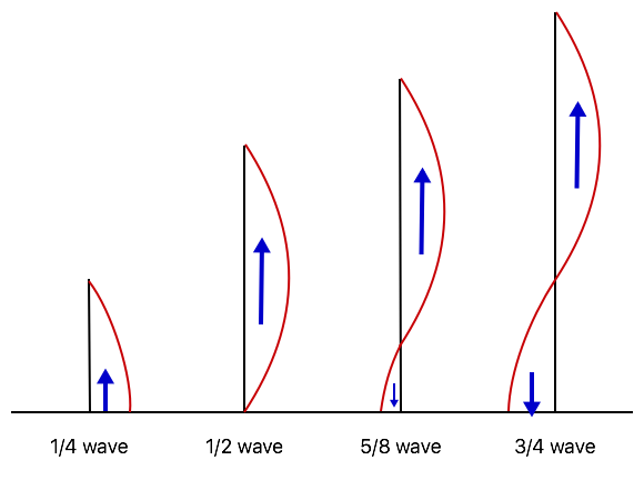
Analysis is very simple for a sinusoidal current on a straight conductor, fed against ground at one end. Notice, however, that antennas longer than 1/2 wavelength begin to show more current at the base that is out of phase with that in the upper section of the radiator. That’s what contributes to the high angle lobes we see in the patterns.
So what makes the difference between a 1/2 wave vertical and a 5/8 wave vertical that would account for the difference in gain? The 5/8 wave antenna has a bit more conductor that is radiating, true, but that is out of phase with the main radiation, so it would actually reduce the radiation at the horizon. The standard explanation is that the out-of-phase portion at the base has low enough current that it doesn’t have a significant effect on the radiation pattern. If we ignore it, that leaves us with the same current distribution as the 1/2 wave vertical, just a bit higher in the air.
a better understanding
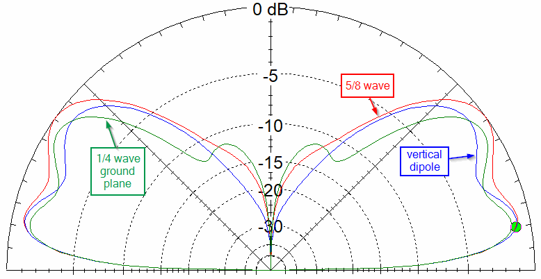
If so, what happens if we elevate the 1/2 wave vertical (like a vertical dipole) so the top of the two antennas are at the same height? Let’s add a 1/4 wave ground plane with sloping radials to our study, like this:
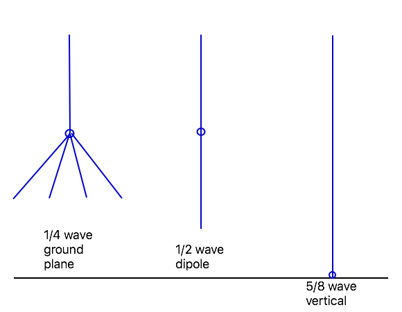
We’ll look at the results over perfect ground to avoid possible modeling quirks…
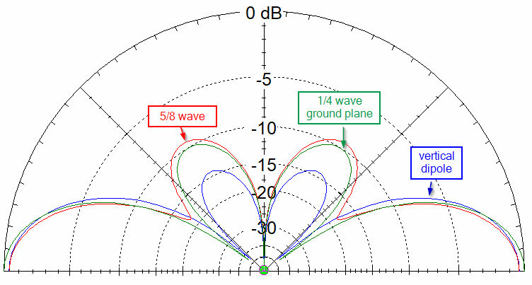
So, does the 5/8 wave vertical still have 3 dB of gain over a 1/4 wave? No. The 1/4 wave antenna actually beats it by a fraction of a dB. The plot of the 1/2 wave vertical dipole is slightly cleaner than the 5/8 wave, but all three are close enough that they might as well be the same antenna. Certainly they are close enough that the decision among them can be made on mechanical and practical factors rather than performance.
This is an important step in our understanding of the 5/8 wave antenna: it is basically a half wave radiator that is elevated slightly above the ground, and any dipole equivalent radiator (which includes the quarter wave ground plane with sloping radials) will work just as well when the points of maximum current are at the same height.
Remember, one of the original constraints of Ballantine’s analysis was that the feedpoint was at ground level. If that isn’t a requirement, then 5/8 wavelength has no advantage over many other antennas.
performance in free space
Another of Ballantine’s constraints was that the antenna was over an infinite, perfectly conducting ground. Yet, we often see such antennas installed for VHF with quarter wave radials, or on the finite roof of a car. Is that good enough?
Let’s consider the situation in free space, as it might apply to elevated antennas.
One problem, of course, is that, when we remove the ground, we need to provide some other conductor to feed the antenna against. So here I’ve added 4 radials, each 1/4 wavelength long, to the feedpoint of the 5/8 wave radiator. The 1/2 wave antenna is a center fed dipole (it can be fed off-center with the same result), and the 1/4 wave ground plane uses 4 sloping radials. With that caveat, let’s see how they compare:
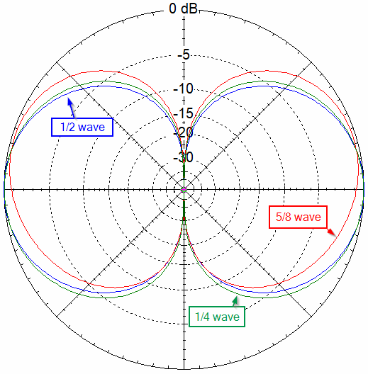
The 5/8 antenna has a bit of an up-tilt to the pattern, due to the out-of-phase current at the feedpoint, and this reduces the radiation at the horizon slightly. Otherwise, there isn’t much to choose among them.
sloping radials
But we used sloping radials on the 1/4 wave ground plane, which improved the radiation slightly (besides improving the SWR). Wouldn’t that help the 5/8 wave vertical? Lets try it…
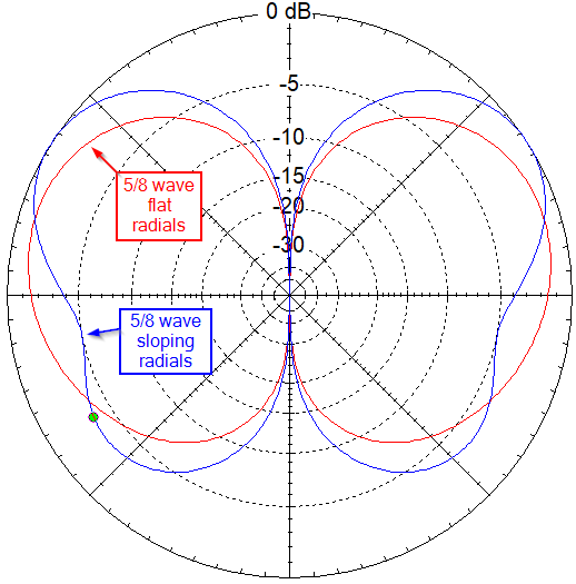
No, that certainly doesn’t help! The reason is that the current in the radials is out of phase with that at the top of the radiator, resulting in something closer to the 3/4 wave vertical that we looked at initially.
ground plane size
The original design assumed an infinite extent of ground. If we make our ground plane larger, does that help?
Consider the mechanism that is responsible for the gain, as shown in the drawing below. Radiation from the center of the current distribution travels up at some angle as a direct wave. It also travels down at the equivalent negative angle and reflects off the ground, with the reflected wave leaving the ground at the same angle as the direct wave. When these arrive at the receiver in phase, they reinforce each other, providing gain.
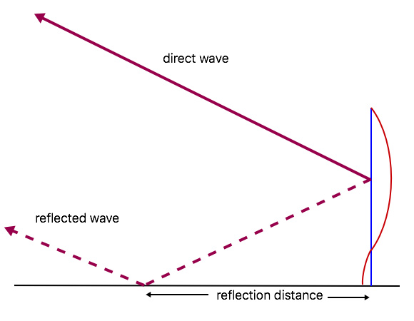
For a 5/8 wave antenna, the center of the current distribution is 3/8 wavelength above the ground. We can then calculate the reflection distance for any vertical angle as 3/8 wavelength divided by the tangent of the desired angle. For example, for radiation at 10 degrees above the horizon, the reflection distance is:
0.375 / tan( 10 degrees ) = 2.13 wavelengths, or more than 3 times the length of the radiator.
At 5 degrees it is twice that. In practice, it will need to be somewhat larger to reflect the radiation from the full antenna. Few installations will provide a large enough ground plane to achieve the possible gain, even at VHF.
Note that this drawing also helps to understand one of the issues with the patterns over real ground: at low angles (below the “pseudo-Brewster Angle”) there is a phase shift in the ground reflection due to imperfect conductivity of the soil, so the direct and reflected waves don’t necessarily reinforce each other at the receiver.
performance of elevated antennas
Now that we are looking at antennas that aren’t connected to ground, we can model performance when all three antenna types are elevated over real ground (which avoids many of the modeling problems). Let’s put the top of each antenna up 1 wavelength:
We could run more plots for different heights, but in general there is little difference between the 5/8 wave vertical and a 1/2 wave (dipole or end-fed) with the top (and thus the center of the current distribution) at the same height above ground.
For elevated installations, the only advantage that the 5/8 wave vertical has over 1/4 and 1/2 wave antennas is the increased height when the feedpoint is fixed, such as a mobile whip on the roof of a car. My experience in switching between a 5/8 wave and 1/4 wave whips on the roof of my van is that there is a slight advantage, perhaps 1 dB, in favor of the 5/8 wave, as long as the longer whip remains vertical at speed. (If it bends, that can change the polarization.)
summary
In spite of almost a century of use, the 5/8 wave vertical doesn’t provide the expected gain in many typical ham installations. It might do a bit better when ground mounted over soil, but a vertical dipole, end-fed half-wave antenna, or a quarter wave ground plane with sloping radials will work just as well when the tops of the antennas are at the same height.
When you are limited to having the feedpoint at ground level, it is worth considering. If you are hanging a wire from a tree branch, it may be just as easy to pull up some other type of antenna that can be fed directly with coax.
improper applications of a 5/8 wave antenna
Because of the mythology around the 5/8 wave antenna, they get used in (or at least compared to) many situations where they simply don’t apply. Some examples:
- A long telescoping antenna on a VHF or UHF hand-held radio. The radio serves as the ground plane, so this is equivalent to using sloping radials: it isn’t optimum. A 1/2 wave antenna is shorter, works better, and puts less stress on the coax connector.
- The radiator of a J-pole. I asked the manufacturer why, and apparently “everybody knows that a 5/8 wave is better” than the normal 1/2 wave radiator. No, in this case, it isn’t.
- Winding 5/8 wavelength of wire on a 1/8 wave fiberglass rod as a reduced-length mobile antenna, and calling it a “5/8 wave antenna”. No, it is a 1/8 wave antenna. It will not act like a 5/8 wave antenna, even if you could put it over an infinite, perfectly-conducting ground plane.
- Recently I found a web page extolling the virtues of a 0.64 wavelength radiator, and how much better it was than a 5/8 wave (which is only 0.625 wavelengths). True, it does have a bit more gain, but that is at about 35 degrees above the horizon (when the top of the antenna is at 1 wavelength). It actually is a bit worse than a 5/8 wave at low angles, which is generally where we want maximum radiation. The half wave dipole and 1/4 wave ground plane with sloping radials are still a bit better, although the differences are relatively small.
BACK TO:
RELATED ARTICLES:
analysis of current distribution on a wire
the importance (or not) of antenna resonance
understand the quarter wave ground plane
building a ground plane antenna
EXTERNAL LINKS:
W4RNL: The 5/8-Wavelength Antenna Mystique
VK2OMD: Matching a 5/8 wave vertical