adventures with small feedlines
last updated 1 October 2025.
The title says this is about small feedlines, and that is indeed what it focuses on, but the lessons learned about the causes of feedline loss and other factors can be applied to other sizes of feedline, and especially in characterizing unknown types, or cables that aren’t intended for RF use.
The word “adventure” has a particular meaning for me: it means I do not know what is going to happen, or where I am going to end up. This investigation certainly took me to some unexpected places.
history
This story starts almost half a century ago, when I first got a QRP HF transceiver (Heathkit HW-8) and took it backpacking. To save weight and cost, I used some small speaker cable for feedline for my dipoles. I made a number of contacts, but still clearly remember sitting in the wilderness, hearing KC4AAA from the South Pole calling CW on 40m with no takers. He couldn’t hear my signal, no matter how hard I pressed the key, because my transmitter wouldn’t load into the antenna: the SWR was too high. (This was well before the days of built-in autotuners.)
The problem turned out to be the feedline: it was close to 1/4 wavelength on 40m, and the characteristic impedance around 130 ohms or so. That meant that the radio was looking into something over 300 ohms, rather than 50 ohms. I switched to small RG-174 coax cable instead, which worked well over the years.
That antenna kit still works, although I decided it was time for an upgrade. Over the years of living in areas with a lot of high-tech industry, I’ve picked up various types of surplus wire and cable. When I returned from a recent hamfest with a small box of coax cable cable pieces having different colored stripes, but no other markings, I decided to measure their characteristics, to compare them to the other types of cables that I had accumulated, as well as my well-traveled pieces of RG-174. Some of that made it into my feedline data tables. But there was a lot more to learn about coax losses, and some surprises along the way.
So this article is as much about how to measure the characteristics of feedlines (of any size), and what factors contribute to the losses, as it is about the specific cables I tested. These are tools that any ham can use in their own adventures.
objective
The objective in choosing a feedline is to make a reasonable compromise among weight, loss, cost, availability, and other factors, given the expected operating frequencies and required length.
It’s very important here to point out that personal preferences and conditions are going to factor in to any such compromise, so there is no expectation that a solution that works for one ham is going to be suitable for someone else. I will comment on the decisions that I came to, given my particular operating interests and the materials available to me, but I want to focus on the process, and how to gather the information required to make your own decision.
Some of the criteria to consider:
Weight is an important factor when one is carrying one’s equipment some distance on your back. The cables that I’m considering here weigh between 75 grams ( 2.6 ounces ) and 370 grams ( 13 ounces ) for a 10m ( 33 foot) length (excluding connectors). Lighter cables tend to have higher losses, especially for coax cables, but not universally. Shorter cables are often practical, depending on where you are operating. How much extra weight you are willing to carry likely will depend on the distance you need to carry it, your physical condition, etc.
Other physical characteristics may be important as well, such as flexibility (how small can you bundle it up?), resistance to kinking, weather resistance, risk of damage if it is stepped on, and how well it maintains those capabilities in heat and cold. For example, cables may be stiffer in the cold, and foam cables may be more likely to deform if stepped on after being in the hot sun. Such factors are rarely specified on the data sheet, and may need to be learned from experience.
Feedline Loss is often one of the most critical factors, especially on the higher frequency bands. It varies with frequency and cable length. When comparing two feedlines, it is quite possible that one will have lower loss on one band but higher loss on a different band. We’ll talk a lot more about loss later in this article. But an important point is for you to determine what amount of loss is acceptable in your particular circumstances. For example, in Feedline Loss vs. Antenna Height, raising my 20m antenna from 6m to 8m gives about 0.6 dB extra gain at 30 degrees vertical angle, and a 2 dB improvement at 10 degrees, in spite of the 0.2 dB of additional loss in the longer cable, and an additional weight of 30 grams (1 ounce). (That assumes that I have the required supports for the higher antenna, of course.) In practice, cables with losses of 1 to 1.5 dB or so have been quite satisfactory, even at QRP power levels.
While coax cable with an impedance of 50 ohms is popular and convenient, 75 ohm cables may have lower losses, and some small two-conductor cables may be pressed into service for their light weight and low cost (or availability) that have even higher impedances. There are several ways that these can be used with a 50 ohm transmitter without an antenna tuner: see using 75 ohm coax.
Balanced lines, like twinlead, speaker cable, or a twisted pair, are sometimes preferred to coax cable for feeding multiband antennas such as doublets.
Cost and availability are important factors as well. It doesn’t matter how good a particular cable is if you can’t obtain it within the limits of your budget. Some of these cable types aren’t carried by the standard ham stores, and might only be available from industrial suppliers on a 300m ( 1000 ft ) spool. Sometimes you have to improvise with whatever you can find locally, like old telephone wire or power cords. You may not be able to obtain the specific cable types that I describe here, but I hope it gives you the ability to make a reasonable choice among the options that are available to you.
Manufacturers’ data sheets are a useful place to start, and I have tried to provide links to data sheets where possible in this article for reference. But they don’t always provide all the information we might want. For example, some manufacturers don’t specify cable loss below 30 or 50 MHz, leaving us to guess the actual losses in the lower HF range. And some cables don’t have any manufacturer’s identification on them. So we may have to measure them ourselves.
measurements
Some measurements are fairly easy to make: cable diameter, for example, can be measured with with a tape measure or comparison to other common objects of known sizes. Wire diameter is easier with a micrometer or pair of calipers perhaps. A kitchen scale is sufficient to get the weight.
But measurements of the RF characteristics require a bit more equipment. I’m going to split the following topics out into separate articles, so those who aren’t interested in the technical details can skip them for now (and others can skip this article and just read those topics if that is their interest).
characteristic impedance
The characteristic impedance (often labeled Z0) of a feedline tells you what sort of matching problems you may encounter when using the feedline, and is also important in calculating the losses. 50 ohm feedlines are convenient in most common ham systems, especially when wanting to avoid using an antenna tuner. But sometimes we may use a line of a different impedance due to lower losses or availability.
measuring the characteristic impedance (Z0) of a feedline
velocity factor
Velocity factor is important when cutting a feedline to a specific length for matching. We usually don’t worry about it for 50 ohm cables, but we use it when cutting a cable to 1/4 or 1/2 wavelength.
matched line loss (MLL)
Matched line loss is the inherent loss in the cable when matched to its characteristic impedance. It typically increases with frequency, so is often specified at discrete frequencies, or shown on a plot. It is typically given in dB loss per some unit length, which is then scaled to the desired length.
There are many sources of loss data for common transmission lines: tables and calculators on line, plots in reference books, etc. If you compare them, you may find that they don’t all agree. Sometimes this is because products with the same type number from different manufacturers aren’t all the same. Sometimes it is due to extrapolating from data for other frequencies. Or the feedline may be damaged (such as water contaminating the braid) that has changed the loss. Or we might be using a product for which there are no RF specifications available (such as speaker cable). That’s why it is often a good idea to measure the actual loss of a line.
There are three major factors that affect the loss of a feedline: the characteristic impedance, the dielectric properties of the insulation, and the resistance of the conductors. At HF and VHF, the dielectric losses are generally small when using polyethylene or PTFE (Teflon®) insulation, so the RF current through the conductor resistance is the major factor. The average current is lower with higher impedance lines, generally giving lower losses, which is why open wire lines can have very low loss. But with coaxial lines the center conductor becomes too small at high impedances (which increases conductor resistance), and 75 ohms is generally the optimum impedance for low-loss coaxial cables.
However, other types of insulation, especially plastics such as PVC that are often used in non-RF cables, can have high dielectric losses: this loss tends to increase more with frequency.
An important aspect of conductor loss is that the AC resistance at the operating frequency may be much higher than the DC resistance. That’s due to “skin effect”, where the current is more on the surface of a conductor rather than in the center. (Some of the “traditional” numbers for the loss of open wire lines have been shown to be unrealistic, possibly because they ignored this factor.) The AC resistance increases with frequency, as less of the conductor is actually used. However, small cables often use copper-clad steel (CCS) for strength, and at lower frequencies where the copper layer is too thin, the RF losses in the steel core will increase the loss.
I discuss this in more detail in factors that affect feedline loss.
Feedline losses also (usually!) increase with higher SWR, but I will address that in a separate article.
comparing losses
After looking at a lot of numbers, I decided that the easiest way to compare the losses of different feedlines is using a graph. That’s because it actually gets complex: sometimes one feedline will have less loss at low frequencies, but another will be better at high frequencies.
For reference, I’m going to use plots for “typical” RG-58 (similar to UR-43) and RG-174 (Belden 8216) for reference. That permits a quick visual comparison for the loss of each cable from 1 to 50 MHz against two of the common alternatives. For some feedline types I only have limited data, and measured data is sometimes noisy (so the graphs may look odd). Here is our reference chart:
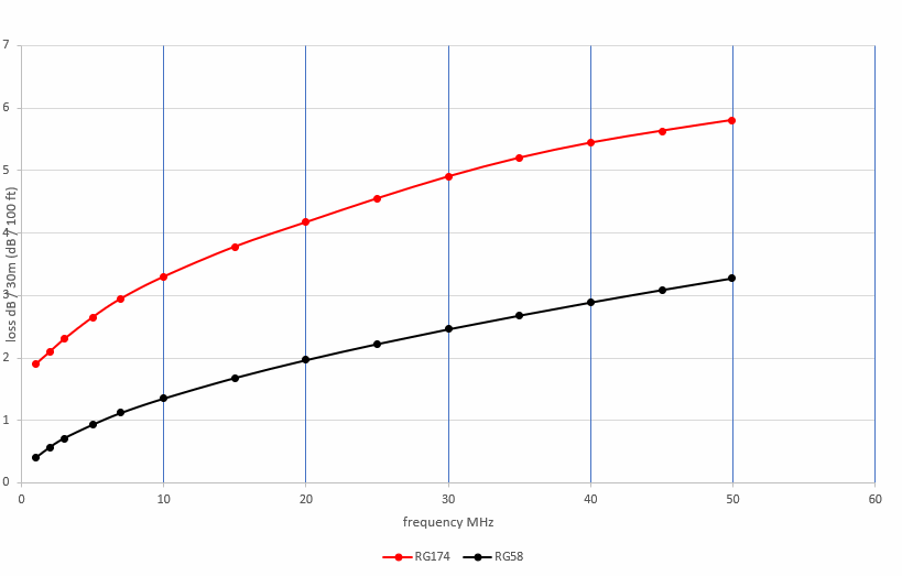
This shows the loss in 30m (100 feet) for RG-58 (lower black line) and RG-174 (upper red line) at frequencies from 1 to 50 MHz. We will use these as reference plots for the other cables in this collection. This makes it easy to compare cable losses at a glance. Typical cables for portable operation may be only 1/3 that length, or less, and the losses in dB scale accordingly.
coaxial cables
I’m going to start with coaxial cables, as I have more data to work with. (I have some limited data on parallel conductor cables like twinlead and speaker cable, but I have more work to do in that area.) All of these are smaller and lighter than RG-58. I’ve provided links to data sheets were available, but these may not be the only manufacturers.
RG-174
RG-174 is probably the most common small cable for lightweight ham operation. Our reference RG-174 cable is 2.5mm ( 0.1 inch ) in diameter, about half the size of RG-58, and 1/3 of the weight. I’m using data for Belden 8216 in this case – other types may show some variation. Here is our reference plot with the addition of actual measurements on two different pieces of RG-174 and a similar (unmarked) piece:
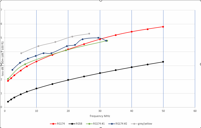
We expect the large difference between RG-58 and RG-174 at the higher HF frequencies due to the size difference, but the difference below 10 MHz is affected by the use of stranded copper-clad steel for the center conductor in the RG-174. Otherwise the two curves would be closer together at 1 MHz. (We’ll see examples of that in the later plots.)
The green line is the original feedline (Belden 8216) from my backpack dipole kit, after 45 years. Given the expected accuracy of the measurements (and the lack of water proofing at the feedpoint), I’d say that is pretty good! The wavy dark blue line is a longer cable simply marked “RG-174”, with no manufacturer or other information. It isn’t a nice neat curve due to measurement noise. My guess is that they used a thinner copper plating on the stranded center conductor, resulting in higher losses at low frequencies.
The grey line at the top is some grey/yellow striped cable with no markings that I found at a local store that “looked like” RG-174: it was 50 ohms, but had somewhat higher losses; again, probably due to less copper thickness on the center conductor, judging from the fact that the losses don’t drop as quickly at low frequencies as they do for RG-174.
Be aware that there is a lot of conflicting information around regarding the loss for RG-174 cables. This plot shows the loss data read from a graph in the 1984 ARRL Antenna Book (blue), and from a table in the 2023 edition (green), compared to the reference (red) data:
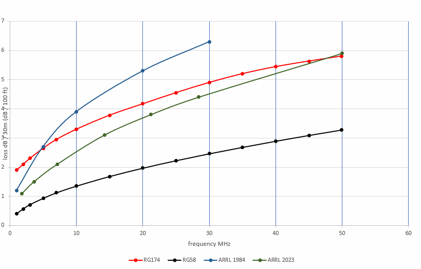
The lower losses shown below 5 MHz are likely due to extrapolating the data for higher frequencies without accounting for losses in the stranded CCS inner conductor at low frequencies. Some online sources may be based on these data, or have other errors. It is worth checking the data from any calculator or table against the manufacturer’s data sheet, or your own measurements.
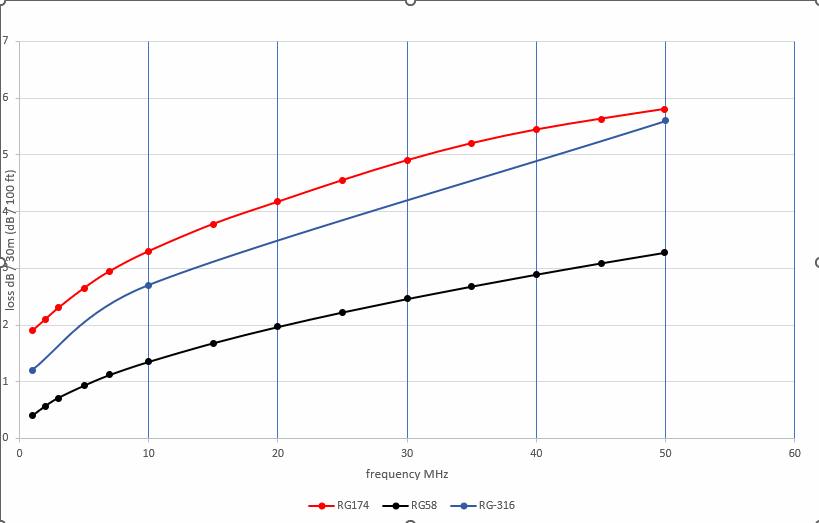
RG-316
RG-316 (Belden 83284) is a PTFE (Teflon®) high temperature version of RG-174. Losses are somewhat lower. It still uses stranded copper-clad steel for the center conductor, but it is silver plated, which reduces the loss. (The curve shows a straight line between 10 and 50 MHz, because those are the only values given on the datasheet. With more points, it would have a curve similar to the red line.)
RF 100
RF 100 (Belden 7805) is their low-loss version of RG-174 with the same size, and similar weight. It uses a foil shield and foamed insulation, permitting a slightly larger diameter center conductor. (This is the standard approach to making low loss cables of any size.) The center conductor is solid copper, rather than stranded copper-clad steel. This plot is from the data sheet: I don’t have a sample to measure.
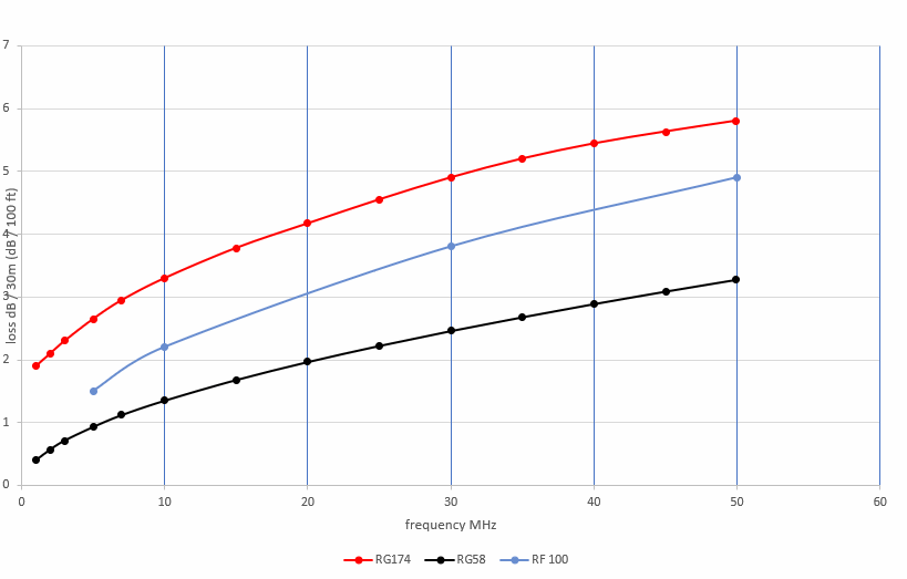
We can see the significant difference at low HF frequencies due to the solid copper center conductor.
LMR-100A
Times-Microwave LMR-100A is their low loss version of RG-174. Unfortunately, the data sheet doesn’t give losses below 30 MHz. I expect the losses are similar to RF 100, but there are several different versions of LMR-100A: Ultra-Flex (LMR-100-UF) has a rubber jacket and stranded center conductor, which sounds more suitable for portable use, but I have not been able to determine whether it uses copper-clad steel or pure copper. That could affect the losses at lower HF frequencies.
RG-178
RG-178 (Belden 83265) is a 50 ohm PTFE cable one size smaller than RG-174 / RG-316, at 1.8mm (0.07 inch) diameter and 2/3 the weight of RG-174. Losses are significantly higher than RG-174. I’ve included RG-179 on the same plot, as there are interesting similarities. Values are from the datasheets.
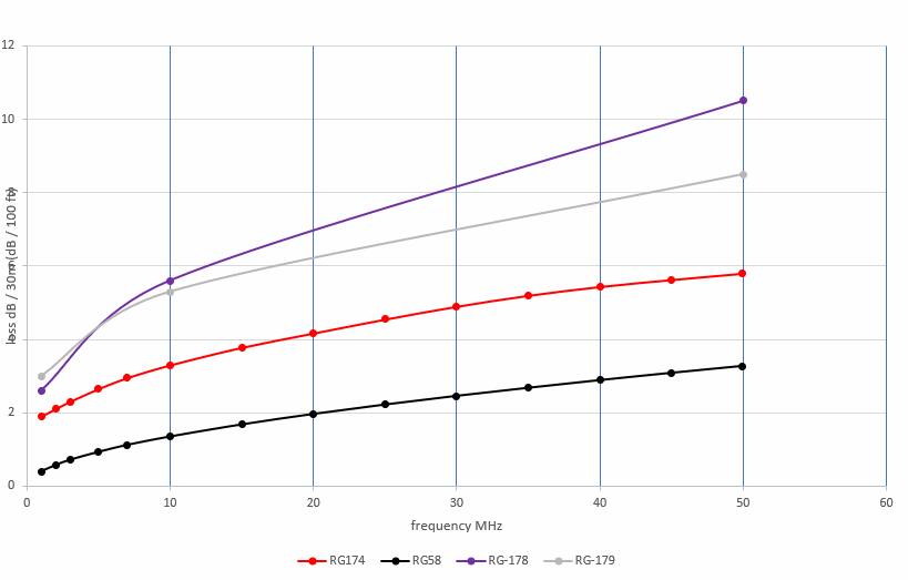
Both cable types have rather high losses, especially above 40m, which will generally limit their use to short lengths, such as for winding baluns.
RG-179
RG-179 (Belden 83264) is a 75 ohm PTFE cable the same size as RG-174 / RG-316. I’ve included it in the plot with RG-178, above. These two cables have the same center conductor: 0.3mm (AWG #30) silver plated stranded copper-clad steel wire. Normally we would expect a 75 ohm cable to have lower losses than a 50 ohm cable of the same size (RG-174 in this case), but here the losses in the steel core of the thin center conductor predominate at low frequencies.
striped cables (Tektronix surplus)
These are white coax cables with colored stripes that I got at a hamfest, used for internal wiring of Tektronix test equipment. It is the same size as RG-174, with a solid copper conductor and PTFE insulation. The solid center conductor makes it less flexible than RG-174, but the losses are lower. Again, we see the difference between the solid copper and stranded copper-clad steel center conductors at 1 MHz. These data were collected from several different pieces with different color stripes.
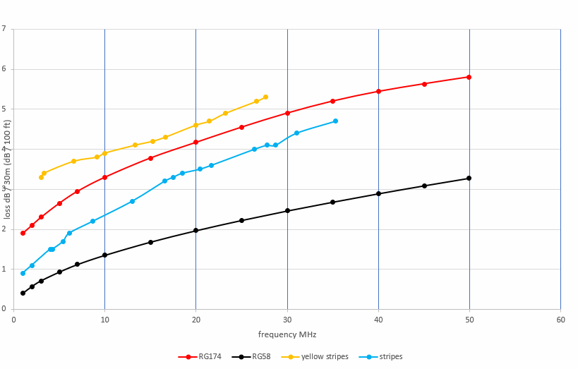
Except that the cables with yellow stripes were 75 ohms rather than 50 ohms, and had higher losses (but slightly better than RG-179), even though they were in the same box with the others. This is another reason why we measure cables that we aren’t sure of.
These cables are a bit stiffer than RG-174, but I’m going to try it out in my upgraded backpack dipole kit to see how it works.
Belden 9221
Belden 9221 is a 75 ohm cable with foam dielectric, the same size as RG-174 and 3/4 the weight. It has a stranded copper center conductor (rather than copper-clad steel). The data sheet values looked good, virtually the same as RF 100, so I cut a piece to 1/2 wavelength on 40m to use with my 75 ohm dipole kit.
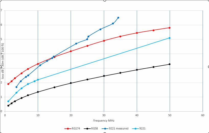
Surprise! The light blue plot shows the data sheet values. The dark blue shows the actual cable when measured had higher loss than the data sheet. The characteristic impedance and velocity factor also didn’t match (even though it came as a remnant on the original spool, and was clearly marked with the type number). My guess is that there wasn’t enough air in the foam dielectric for this spool (or this portion of the spool, at any rate) due to a manufacturing problem (which may be why it was cheap at a hamfest!). It isn’t any worse than RG-174 up to 20m, but not as good as the data sheet led me to believe. In practice, the center conductor is rather fragile, and is now intermittent because the connector wasn’t stiff enough. The resonant length on 40m is about 15m (50 feet), which is longer than I would normally carry, making losses more important than for a shorter cable. This will be replaced.
Belden 9264
A hamfest vendor was selling this marked as a 50 ohm RF cable, so I bought 10m to try out. It is slightly larger than RG-174, but not exactly circular in cross section, as it has a foil shield around the center conductor and a separate drain wire down one side. It is stiffer than most other cables of this size. However, I couldn’t find any reference to it on the Belden website. Further searching found that it is a discontinued audio cable with flameproof polypropylene insulation, rather than polyethylene as is used in most RF cables. And the measured data show the results:
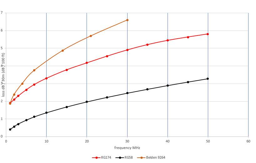
Clearly not very low loss at RF! It certainly wouldn’t be my first choice cable, but might not be too bad on the lower bands if that was what was available.
Belden 735A1
Belden 735A1 is a 75 ohm cable that is a bit larger than RG-174 at 3.3mm (0.13 inches), with a solid copper center conductor and foil shield covered by braid. It is a bit heavier than RG-174, but still only half the weight of RG-58. And the lowest loss of the cables that I tested.
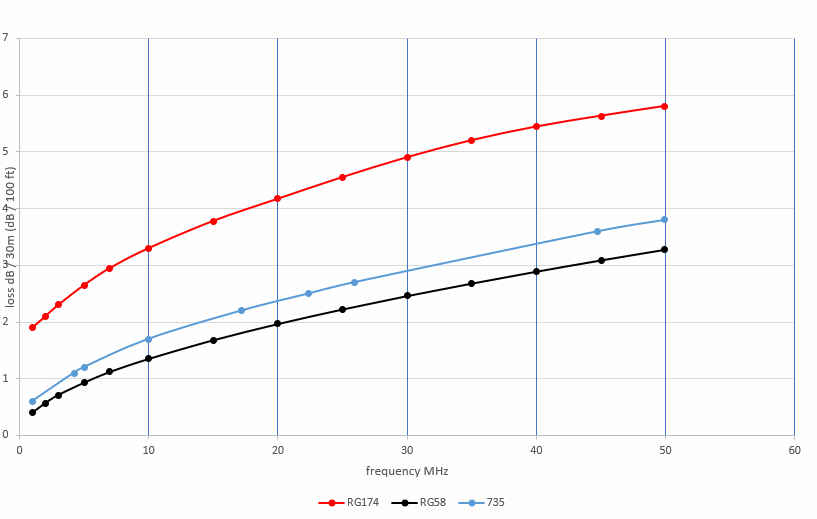
These are the data sheet values. Actual measurements were very close to this plot. Not as flexible as RG-174, and seems more likely to kink, but it will replace the Belden 9221 in that 75 ohm dipole kit that uses a longer cable, for when I may be able to get my antenna up higher. Then I’ll get some experience using it in the field to see how it holds up.
Update: After using the 735A1 coax a few times, it seems to work well. It coils most comfortably 20cm (8 inches) or more in diameter, and I have to use more care when I unwind it, but it hasn’t kinked yet. It seems like a good alternative, especially for higher antennas and/or on the upper HF bands, while still being smaller and lighter than RG-58.
parallel conductor cables
I’ll finish this part later, after I get more measurements.
summary
This has been quite an adventure, and I’m sure it isn’t over yet. I’ve personally learned a lot in the process, and hopefully been able to pass along some useful tools and techniques for evaluating feedlines of any size or type.
I’ll admit that most hams won’t have access to all the cables that I’ve mentioned here. But I’ve included them for two reasons:
- To show that there are many options to the “standard” ham cables
- To show how to evaluate whatever types of cables that you might have available to you.
RG-174 is still a reasonable alternative, especially for lengths less than about 10m (30 feet), and is often less expensive than most other small cables designed for RF use if purchased new. The RF 100 / LMR-100A (or similar types from other manufacturers) would be an excellent alternative when available, as would RG-316, although it likely would be more expensive. RG-178 works well for winding small baluns, but the additional loss might not be worth the weight savings for use as a feedline. The 75 ohm Belden cables 9221 (if it meets the data sheet specs, and with a reinforced plug) and 735A1 have potential, if one is willing to deal with the odd impedances (perhaps not an issue if you are using a tuner anyway) and can find them in suitable quantities. There are many other types out there, too: some, like the Belden 9264, or the yellow striped Tektronix cables, might not be good choices. But now you have the tools to determine how well they might work for you.
If losses are still too high for your application, then you might consider antennas that don’t require as much feedline, such as an end-fed wire perhaps, or vertical full wave loops.
Tip: for coax connectors for odd sized cables, consider RCA plugs (or “phono” plugs – commonly used for audio). I started using them because those were the antenna connectors on my first transceivers (Heathkit HW-12, TenTec Argonaut 505, Heathkit HW-8), and I still find them more convenient for small cables. Adaptors are available to BNC or PL-259 connectors, and the RCA plugs are much easier to repair in the field if they get stepped on, or get some sand caught in them.
back to:
related pages:
measuring characteristic impedance
factors affecting feedline loss
feedline losses vs. height and performance