wire quads
last updated 14 February 2026.
overview
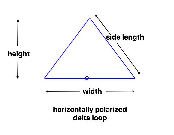
When a full-wave loop is used with square loop parasitic elements, it is often called a “cubical quad” antenna (or just “quad”). Such antennas can be built using other shapes, as described in the section on full wave loops. An array with triangular elements is often called “delta loop”. We’ll use the generic term “quad” for any of these parasitic loop arrays.
Traditional “cubical quad” antennas have been built using wire on some sort of a framework of poles or other supports, but they can be assembled using wire and rope as well, especially if they do not require rotation, using the same general methods as wire yagis. Using a single boom (either rigid, or a rope strung between two trees), the triangular elements with the point at the top are generally the most convenient mechanically, although they don’t always make the best advantage of the boom height. Other shapes are possible, given the available supports.
Full wave loop elements are actually easier to design with than conventional yagis, however, as the shape of the loops can be adjusted to vary the feedpoint impedance, and antennas can be designed for higher impedances to give wider SWR bandwidth. The variation for single loops is shown on the full-wave loop theory page. For these antennas, the parasitic elements change the impedance of the driven elements, then the shapes are adjusted for low SWR with common matching methods.
In general, quad designs are likely to give higher gain than similar wire yagi designs at top heights of 3/4 wavelength over ground or higher, while yagis may have a lower angle of radiation at 1/2 wavelengths. Results at intermediate heights depend on several factors and will need to be modeled for the specific circumstances.
Unless otherwise noted, all dimensions are for 1mm (AWG #18) bare copper wire. Insulated wire will need to be a bit longer.
construction
There are plenty of online references for mechanical construction of rotatable quad antennas, so I will focus more on lightweight designs that may not be easy to rotate, but that may be simpler to construct.
There are two general approaches, particularly for delta loop designs with the point up: a self-supporting boom attached to a tower or mast, and a rope strung between two supports. The rope is more convenient for long antennas. For short antennas, additional spreaders can be used between the bottom corners of the elements, so a single rope (or crossbar from the mast) can be used for each side of the antenna.
Some useful techniques are described in Construction of Wire Loop Antennas.
Note that the two elements are different sizes, and can be arranged relative to each other in different ways (tops at the same height, bottoms at the same height, bottoms of the same width, one centered relative to the other, etc.) Such small differences will have little effect on performance, as long as the perimeters of the loops are maintained.
For horizontal polarization, loops can be fed either at the top center or the bottom center of the driven element, whichever is more convenient mechanically. If the feedpoint is in the middle of a horizontal wire at the bottom of an element, it can be supported by a rope from the boom above it to reduce sag from the weight of the coax and balun.
2-element designs
The 2-element parasitic loop designs can have a wide range of shapes, mechanical structures, impedances, and other characteristics. I’ll show a number of examples, both traditional and less conventional. These may give you some ideas of other designs you might try.
Generally such antennas use a “driven element”, connected to the feedline, and a slightly larger “reflector” as a parasitic element (with maximum radiation in the opposite direction from the reflector). However, there are some occasions where the parasitic element may be tuned as a “director” instead.
Note that these designs are “reasonable”, rather than fully optimized, because different users may have different priorities. For example, I haven’t placed a high priority on Front/Back ratio, but in some applications that may be more important than gain, SWR, or bandwidth, and the design can be adjusted accordingly.
In some cases, I will just provide dimensions for a single band where a particular design might be most useful. Dimensions can be scaled to other bands as desired.
traditional delta loop – 112 ohm feed
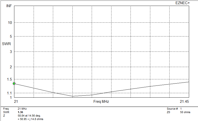
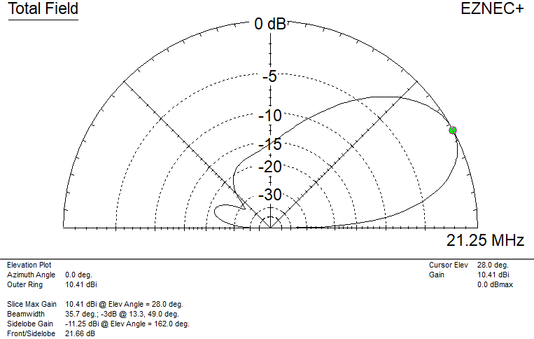
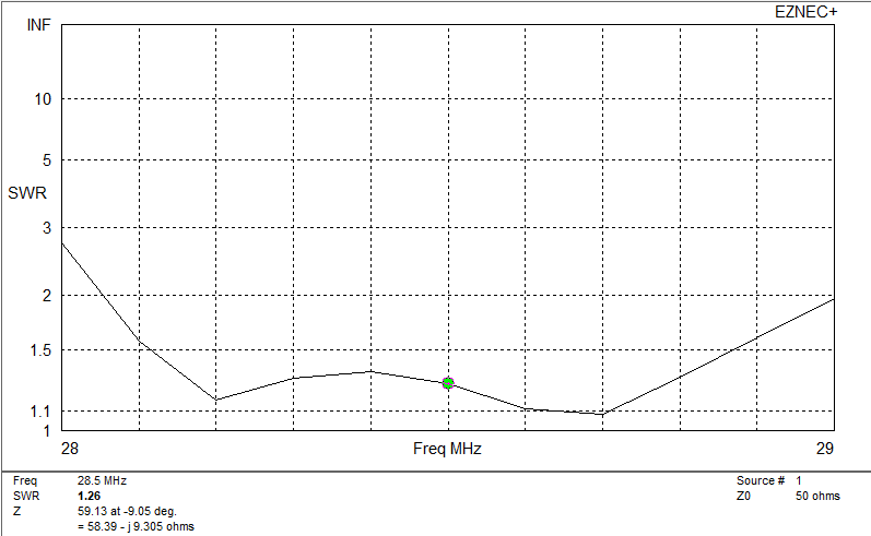
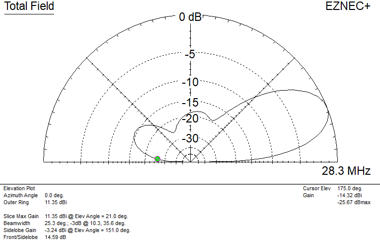
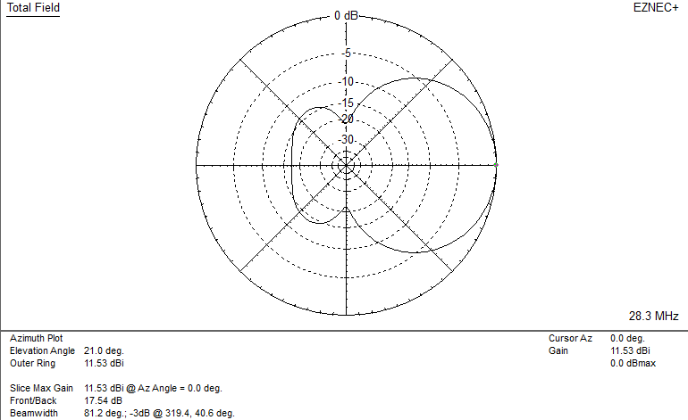
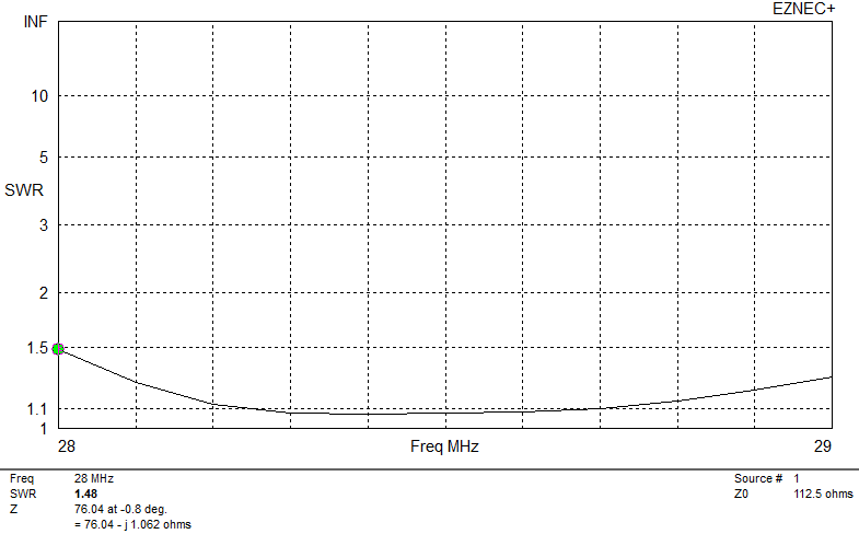
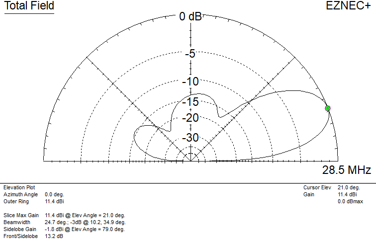
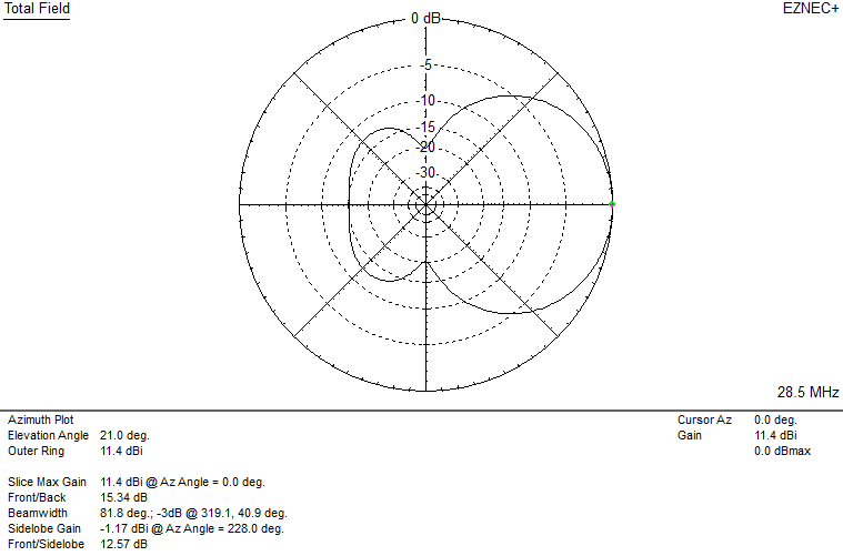
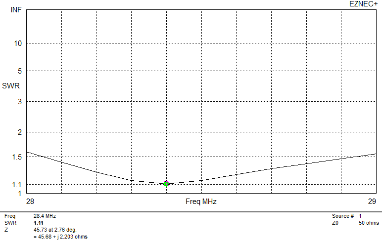
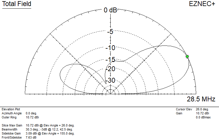
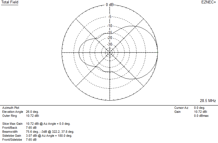
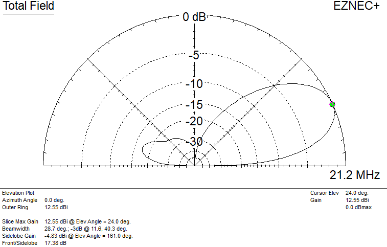
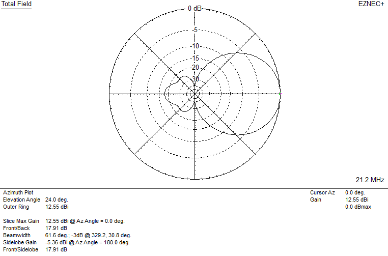
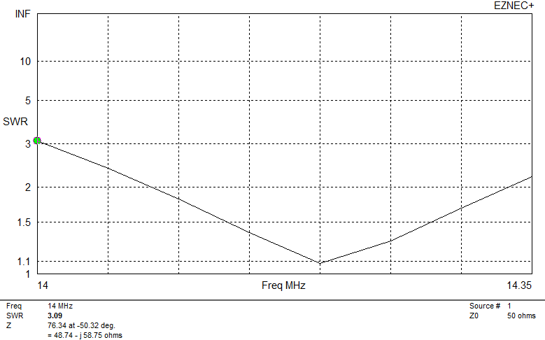
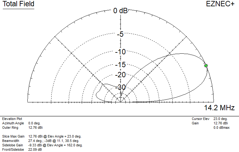
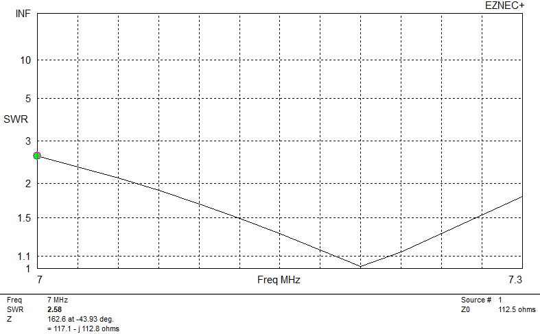
A feedpoint impedance of 112 ohms can be matched to 50 ohms using an electrical quarter wavelength of 75 ohm coax cable. (Lengths given are for a velocity factor of 0.67, typical of solid dielectric coax cable.) These are for wire delta loops with the point up, so they can hang from a boom, although the same dimensions work with the point down, as long as the loop is high enough above ground. Typical SWR and pattern plots (for 15m, details vary somewhat from band to band):

These particular dimensions result in the reflector loop height being slightly shorter than the driven element loop, but wider to use the extra wire length. That is a quirk of how I adjusted them. The antenna will work just as well if the loops have the same height, or the reflector is slightly taller, as long as the wire wire perimeter is held constant. The width of the driven element loop is important for the impedance match.
10m dimensions
For 10m, the antenna SWR is below 1.5 : 1 from 28.2 to 29.0 MHz, rising to 2 : 1 at the band edges.
| reflector side m ( feet ) | 3.585 ( 11.75 ) |
| reflector width m ( feet ) | 4.08 ( 13.4 ) |
| reflector height m ( feet ) | 3.09 ( 10.2 ) |
| reflector perimeter m ( feet ) | 11.25 ( 36.9 ) |
| element spacing m ( feet ) | 1.8 ( 5.9 ) |
| driven element side m ( feet ) | 3.58 ( 11.75 ) |
| driven element width m ( feet ) | 3.63 ( 11.9 ) |
| driven element height m ( feet ) | 2.95 ( 9.67 ) |
| driven element perimeter m ( feet ) | 10.79 ( 35.4 ) |
| design center frequency | 28.5 MHz |
| SWR bandwidth @ 1.5 : 1 kHz | 800 kHz |
| design top height of antenna m ( feet ) | 7 ( 23 ) |
| matching coax length m ( feet ) | 1.8 ( 5.9 ) |
15m dimensions
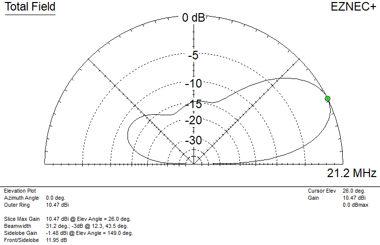
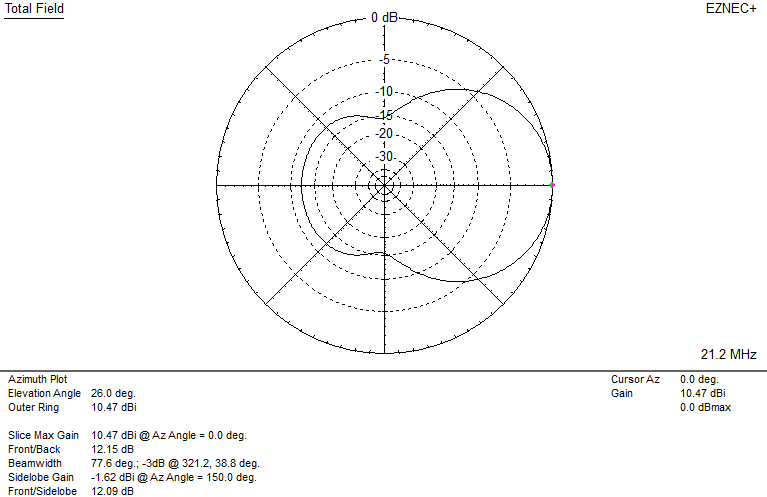
The plots for the 15m version are shown above. The SWR is less than 1.4 : 1 across the band.
| reflector side m ( feet ) | 4.81 ( 15.8 ) |
| reflector width m ( feet ) | 5.48 ( 18.0 ) |
| reflector height m ( feet ) | 3.96 ( 13.0 ) |
| reflector perimeter m ( feet ) | 15.1 ( 49.6 ) |
| element spacing m ( feet ) | 2.42 ( 7.9 ) |
| driven element side m ( feet ) | 4.81 ( 15.75 ) |
| driven element width m ( feet ) | 4.87 ( 16.0 ) |
| driven element height m ( feet ) | 4.15 ( 13.6 ) |
| driven element perimeter m ( feet ) | 14.50 ( 47.6 ) |
| design center frequency MHz | 21.250 MHz |
| SWR bandwidth @ 1.5 : 1 kHz | 600 kHz |
| design top height of antenna | 9 ( 30 ) |
| matching coax length m ( feet ) | 2.42 ( 7.93 ) |
20m dimensions
On 20m, the SWR is 1.5 : 1 or less across the whole band.
| reflector side m ( feet ) | 7.19 ( 23.6 ) |
| reflector width m ( feet ) | 8.19 ( 26.9 ) |
| reflector height m ( feet ) | 5.91 ( 19.4 ) |
| reflector perimeter m ( feet ) | 22.57 ( 74.1 ) |
| element spacing m ( feet ) | 3.30 ( 10.75 ) |
| driven element side m ( feet ) | 7.19 ( 23.6 ) |
| driven element width m ( feet ) | 7.28 ( 23.9 ) |
| driven element height m ( feet ) | 6.2 ( 20.3 ) |
| driven element perimeter m ( feet ) | 21.66 ( 71.1 ) |
| design center frequency MHz | 14.175 MHz |
| SWR bandwidth @ 1.5 : 1 kHz | 350 kHz |
| design top height of antenna | 14 ( 46 ) |
| matching coax length m ( feet ) | 3.6 ( 11.8 ) |
40m dimensions
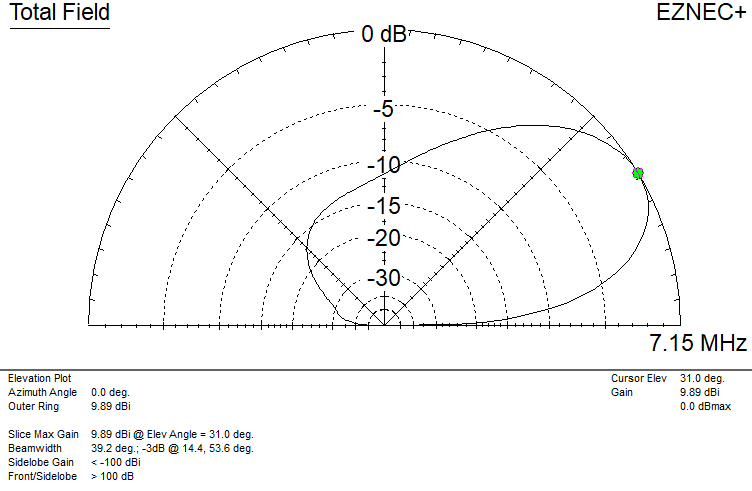
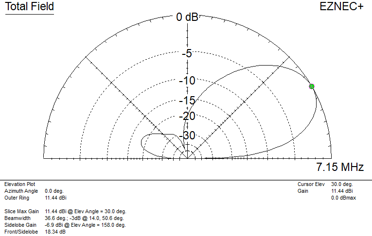
On 40m I placed the antenna at a relatively lower height (in wavelengths) than on the higher bands, and even getting the top to 25m may not be very practical in many situations. The gain suffers and the angle of maximum radiation increases as a result.
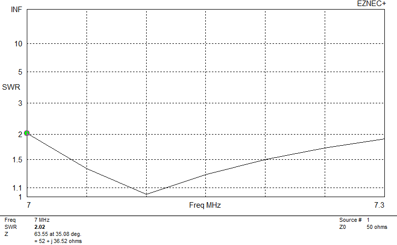

The SWR curve just covers from 7.0 to 7.3 MHz at 2 : 1 SWR or better.
| reflector side m ( feet ) | 14.28 ( 46.8 ) |
| reflector width m ( feet ) | 16.26 ( 53.3 ) |
| reflector height m ( feet ) | 11.74 ( 40.4 ) |
| reflector perimeter m ( feet ) | 44.84 (146.9 ) |
| element spacing m ( feet ) | 6.5 ( 21.3 ) |
| driven element side m ( feet ) | 14.28 ( 46.85 ) |
| driven element width m ( feet ) | 14.46 ( 47.4 ) |
| driven element height m ( feet ) | 12.3 ( 38.5 ) |
| driven element perimeter m ( feet ) | 43 ( 141.1 ) |
| design center frequency MHz | 7.100 MHz |
| SWR bandwidth @ 1.5 : 1 kHz | 180 kHz |
| design top height of antenna m ( feet ) | 25 ( 82 ) |
| matching coax length m ( feet ) | 7.15 ( 23.5 ) |
For the same top height, inverting the elements (so the points are down) will raise the effective height, making the pattern similar to the others in this group, with at least 1 dB improvement over the same dimensions with the point up. The inverted antenna has the same pattern as the original when it is lowered to 20m ( 66 feet ).
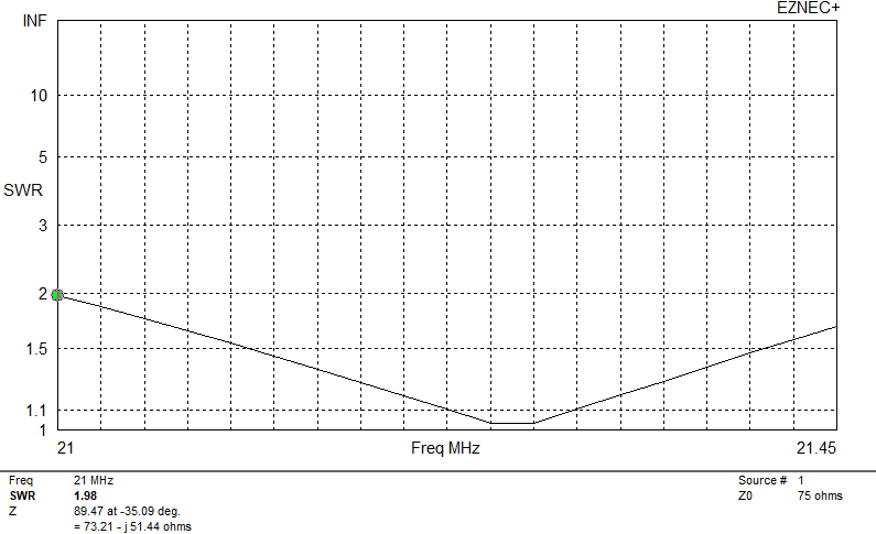
wide bandwidth delta loops: 200 ohm designs
These use the same constructions methods as the 112 ohm designs, but the elements are wider and flatter (close to a right angle triangle). That increases the average height above ground, and the higher impedance gives a wider SWR curve. They are easily matched with a 4 : 1 balun or a quarter wavelength of 100 ohm feedline. (The latter might be 2 pieces of 50 ohm coax in parallel, or twisted pair from computer networking cable. The driven element can be adjusted slightly to use 93 ohm RG-62 coax, or American “zip cord” power cable, which is often around 106 ohms.)
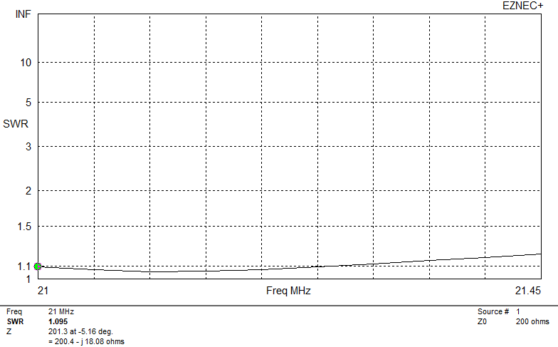
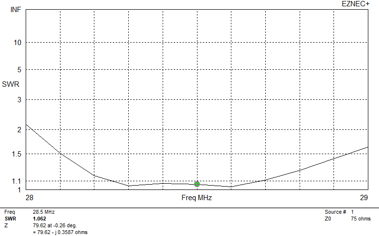
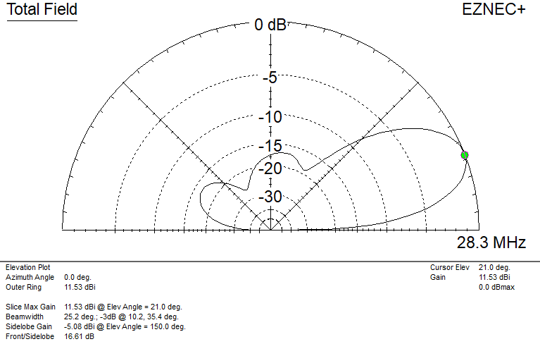
Sample plots (these are for 15m):
10m dimensions
On 10m the SWR is under 1.5 : 1 across the entire band, and less than 1.2 : 1 from 28.0 to 29.0 MHz. Gain is similar to the 112 ohm antennas, although the front/back ratio has not been optimized on these designs.
| reflector side m ( feet ) | 3.30 ( 10.8 ) |
| reflector width m ( feet ) | 5.085 ( 16.7 ) |
| reflector height m ( feet ) | 2.1 ( 6.9 ) |
| reflector perimeter m ( feet ) | 11.69 ( 38.3 ) |
| element spacing m ( feet ) | 1.7 ( 5.6 ) |
| driven element side m ( feet ) | 2.98 ( 9.75 ) |
| driven element width m ( feet ) | 4.16 ( 15.3 ) |
| driven element height m ( feet ) | 1.86 ( 6.1 ) |
| driven element perimeter m ( feet ) | 10.62 ( 34.8 ) |
| design center frequency MHz | 28.5 MHz |
| SWR bandwidth @ 1.5 : 1 kHz | 2000 kHz |
| design top height of antenna | 7 ( 23 ) |
15m dimensions
The SWR of this antenna is less than 1.2 : 1 across the whole band.
| reflector side m ( feet ) | 4.43 ( 14.5 ) |
| reflector width m ( feet ) | 6.83 ( 22.4 ) |
| reflector height m ( feet ) | 4.18 ( 13.7 ) |
| reflector perimeter m ( feet ) | 23.19 ( 76.1 ) |
| element spacing m ( feet ) | 2.3 ( 7.5 ) |
| driven element side m ( feet ) | 4.00 ( 13.1 ) |
| driven element width m ( feet ) | 6.26 ( 20.5 ) |
| driven element height m ( feet ) | 2.50 ( 8.2 ) |
| driven element perimeter m ( feet ) | 14.26 ( 46.7 ) |
| design center frequency MHz | 21.200 MHz |
| SWR bandwidth @ 1.5 : 1 kHz | 1300 kHz |
| design top height of antenna | 9 ( 20 ) |
20m dimensions
Even on 20m, the SWR of these antennas is 1.2 : 1 or better across the entire band.
| reflector side m ( feet ) | 6.55 ( 21.5 ) |
| reflector width m ( feet ) | 10.09 ( 33.1 ) |
| reflector height m ( feet ) | 4.18 ( 13.7 ) |
| reflector perimeter m ( feet ) | 23.19 ( 76.1 ) |
| element spacing m ( feet ) | 3.4 ( 11.2 ) |
| driven element side m ( feet ) | 5.98 ( 19.6 ) |
| driven element width m ( feet ) | 9.36 ( 30.7 ) |
| driven element height m ( feet ) | 3.72 ( 12.2 ) |
| driven element perimeter m ( feet ) | 21.32 ( 69.9 ) |
| design center frequency MHz | 14.15 MHz |
| SWR bandwidth @ 1.5 : 1 kHz | 800 kHz |
| design top height of antenna | 14 ( 46 ) |
40m dimensions
Because of the higher average height, the 200 ohm version doesn’t suffer quite as much from the lower height as the 112 ohm version does, and gives about 1 dB improvement at low angles.
On 40m this antenna still manages an SWR of 1.5 : 1 or better across the 7.0 – 7.3 MHz band.
| reflector side m ( feet ) | 12.9 ( 42.3 ) |
| reflector width m ( feet ) | 19.9 ( 65.2 ) |
| reflector height m ( feet ) | 8.22 ( 27 ) |
| reflector perimeter m ( feet ) | 45.7 ( 149.8 ) |
| element spacing m ( feet ) | 6.8 ( 22.25 ) |
| driven element side m ( feet ) | 11.7 ( 38.4 ) |
| driven element width m ( feet ) | 18.3 ( 60.1 ) |
| driven element height m ( feet ) | 7.3 ( 23.9 ) |
| driven element perimeter m ( feet ) | 41.7 ( 136.9 ) |
| design center frequency MHz | 7.15 MHz |
| SWR bandwidth @ 1.5 : 1 kHz | 300 kHz |
| design top height of antenna | 25 ( 82 ) |
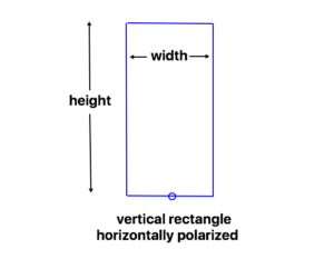
tall and skinny rectangular quads
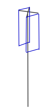
A tall, skinny loop gives some added gain, but requires more height. Designs are given for 50, 75, or 112 ohm feed options. They are narrow enough that a self-supporting framework at the top can support the whole antenna.
Because of the required height and practical spreader sizes, I’m only giving dimensions for 10m, although they can be scaled to other bands. Gain is similar for all three impedances, perhaps 0.5 dB better than preceding delta loop designs. As usual, the higher impedances give a wider SWR bandwidth, but also require longer spreaders.
50 ohm version
The coupling between the two elements for this design provides a wider bandwidth than for many other 50 ohm quad designs. Because it is tall, a top height of 8m ( 26 feet ) or more is recommended on 10m, so that the bottom is at least half the height of the top of the antenna. This limits its use on the lower bands unless very tall supports are available.
| reflector width m ( feet ) | 1.4 ( 4.6 ) |
| reflector height m ( feet ) | 4.13 ( 13.5 ) |
| reflector perimeter m ( feet ) | 11.06 ( 36.2 ) |
| element spacing m ( feet ) | 2 ( 6.5 ) |
| driven element width m ( feet ) | 1.4 ( 4.6 ) |
| driven element height m ( feet ) | 4.05 ( 13.25 ) |
| driven element perimeter m ( feet ) | 10.9 ( 35.7 ) |
| design center frequency MHz | 28.5 MHz |
| SWR bandwidth @ 1.5 : 1 kHz | 750 kHz |
| design top height of antenna | 8 ( 26 ) |

75 ohm version
A bit wider bandwidth, to match 75 ohm coax.
| reflector width m ( feet ) | 1.6 ( 5.25 ) |
| reflector height m ( feet ) | 3.95 ( 13.0 ) |
| reflector perimeter m ( feet ) | 11.1 ( 36.8 ) |
| element spacing m ( feet ) | 2 ( 6.5 ) |
| driven element width m ( feet ) | 1.6 ( 5.25 ) |
| driven element height m ( feet ) | 3.87 ( 12.7 ) |
| driven element perimeter m ( feet ) | 10.94 ( 35.9 ) |
| design center frequency MHz | 28.5 MHz |
| SWR bandwidth @ 1.5 : 1 kHz | 850 kHz |
| design top height of antenna | 8 ( 26 ) |
112 ohm version
A top support frame for this design would be square. These can be matched to 50 ohm coax using 1/4 wavelength of 75 ohm coax. Matching section lengths are the same as for the 112 ohm conventional delta loops.
| reflector width m ( feet ) | 2 ( 6.5 ) |
| reflector height m ( feet ) | 3.6 ( 11.8 ) |
| reflector perimeter m ( feet ) | 11.2 ( 36.6 ) |
| element spacing m ( feet ) | 2 ( 6.5 ) |
| driven element width m ( feet ) | 2 ( 6.5 ) |
| driven element height m ( feet ) | 3.48 ( 11.4 ) |
| driven element perimeter m ( feet ) | 10.96 ( 35.4 ) |
| design center frequency MHz | 28.5 MHz |
| SWR bandwidth @ 1.5 : 1 kHz | 1200 kHz |
| design top height of antenna | 8 ( 26 ) |
single-support quads
There are several ways to create a 2-element quad where the elements come close together at the top to hang from a single center support. This has limitations for horizontal polarization, as the close spacing between the two elements at a current maximum reduces the potential gain. But here are a couple options for specific applications.
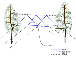
10m single support 2-element delta loop
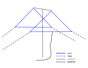
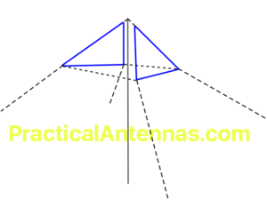
This antenna is comprised of two triangular loops, like the traditional 2-element delta loops, but the tops of the loops are tied to the top of the support mast with short ropes or a short spreader, while the bases of the loops are pulled out away from the mast by the bottom support ropes. The drawing below shows additional ropes connecting the corners of the two loops – these help to maintain the proper spacing. The antenna can be fed in the top corner of the driven element, so the coax can be supported by the mast, or in the center of the bottom wire. The feedpoint impedance is 112 ohms, to be matched using 1/4 wavelength of 75 ohm coax.
delta loop quad
In the table below, the dimensions are given for each wire loop, and for the horizontal spacing between the bottom wires. The base of the antenna is close to square, and it could be adapted to have the support ropes also serve as guy ropes for the mast. As usual, feel free to use this as a starting point for further optimization to meet your needs.
| reflector side m ( feet ) | 3.6 ( 11.8 ) |
| reflector width m ( feet ) | 4.0 ( 13.1 ) |
| reflector perimeter m ( feet ) | 11.2 ( 36.75 ) |
| element spacing m ( feet ) | 3.7 ( 12.1 ) |
| driven element side m ( feet ) | 3.51 ( 11.5 ) |
| driven element width m ( feet ) | 4.0 ( 13.1 ) |
| driven element perimeter m ( feet ) | 11.02 ( 36.1 ) |
| design center frequency MHz | 28.5 MHz |
| SWR bandwidth @ 1.5 : 1 kHz | 900 kHz |
| design top height of antenna | 7 ( 23 ) |
Plots for 2-element 10m single support delta loop quad.
vertically polarized wire quad
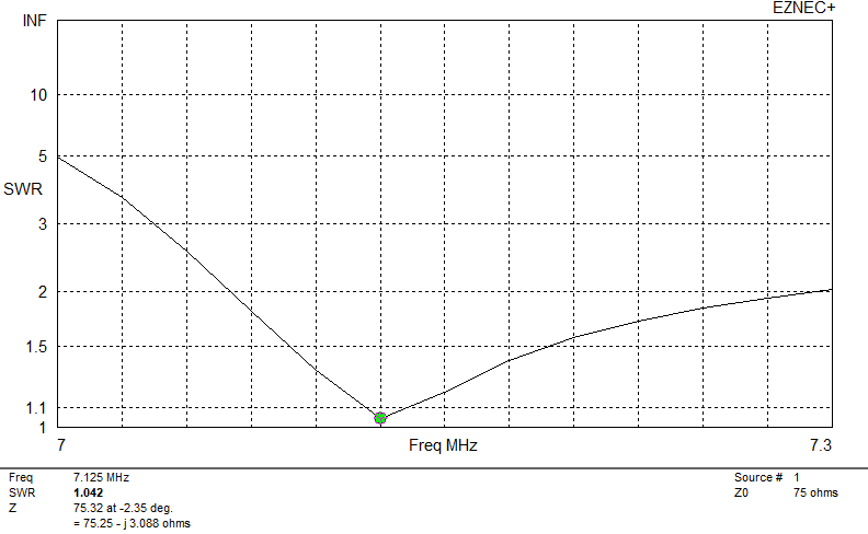
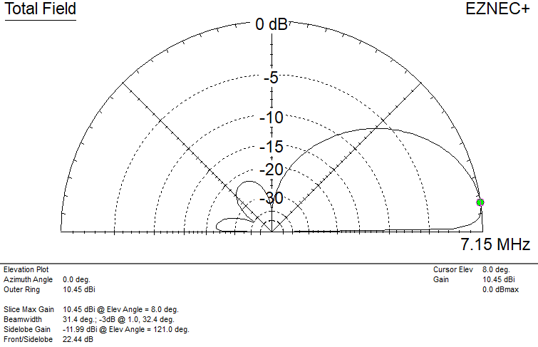
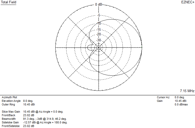
When you can set your antenna up looking across salt water in the target direction, say, from Ho’okipa, Kodiak, or Ham’s Bluff, then a vertically polarized signal can work very well over long distances. The same principles of building delta loop quads are used, but low heights are not as much of a limitation (as long as the bottom wire isn’t a danger to people passing by). The feedpoint is connected to one side of the driven element 1/4 of the perimeter down from the top of the antenna.
Note that the patterns for this antenna are calculated over salt water. The wire sized used is 2mm ( AWG #12 ).
| reflector side m ( feet ) | 13.33 ( 43.75 ) |
| reflector width m ( feet ) | 17.84 ( 58.5 ) |
| reflector height m ( feet ) | 9.9 ( 32.5 ) |
| reflector perimeter m ( feet ) | 44.5 ( 146 ) |
| element spacing m ( feet ) | 6 ( 20 ) |
| driven element side m ( feet ) | 13.05 ( 42.8 ) |
| driven element width m ( feet ) | 17 ( 55.75 ) |
| driven element height m ( feet ) | 9.9 ( 32.5 ) |
| driven element perimeter m ( feet ) | 43.1 ( 141.4 ) |
| design center frequency MHz | 7.125 MHz |
| SWR bandwidth @ 1.5 : 1 kHz | 100 kHz |
| design top height of antenna | 12.9 ( 42 ) |
3-element quads
Adding a second element (a “director”) to a quad is not just a matter of sticking a slightly smaller element in front of a 2-element design. The coupling among the elements changes, and the director generally lowers the feedpoint impedance as it increases the gain, unless the spacings are adjusted as well.
A good starting point are the design formulas from the late W4RNL, used in this calculator. This includes corrections for the wire diameter (don’t trust any quad calculator or formula that doesn’t ask you the wire size). The supporting articles give a lot of good information on quad behavior vs. frequency as well.
If I tried to give all the dimensions for all the variants, I’ll never get this published. So I’ll just put some examples here, and add further data as I get a chance. These will give you an idea of some options, and can be scaled to other bands as desired. Note that the heights and wire sizes aren’t the same as my other designs, so they aren’t directly comparable.
Many longer quad designs are suitable for direct 50 or 75 ohm feed, but a common problem with that approach is operating bandwidth.
15m 3-element 75 ohm delta loop quad
This is derived from the W4RNL models. It uses 1.6 mm ( AWG #14 ) bare wire, which improves performance somewhat. It just covers the 15m band at under 2 : 1 SWR with a 75 ohm feedpoint impedance.
| reflector side m ( feet ) | 4.33 ( 14.2 ) |
| reflector width m ( feet ) | 6.42 ( 21.1 ) |
| reflector height m ( feet ) | 2.9 ( 9.5 ) |
| reflector perimeter m ( feet ) | 15.08 ( 49.5 ) |
| reflector-driven element spacing m ( feet ) | 2.75 ( 9.0 ) |
| driven element side m ( feet ) | 4.19 ( 13.75 ) |
| driven element width m ( feet ) | 5.92 ( 19.4 ) |
| driven element height m ( feet ) | 2.96 ( 9.7 ) |
| driven element perimeter m ( feet ) | 14.3 ( 46.9 ) |
| reflector-director spacing m ( feet ) TOTAL ANTENNA LENGTH | 6 ( 20 ) |
| director side m ( feet ) | 4.12 ( 13.5 ) |
| director width m ( feet ) | 5.64 ( 18.5 ) |
| director height m ( feet ) | 3 ( 9.8 ) |
| director perimeter m ( feet ) | 13.88 ( 45.5 ) |
| design center frequency MHz | 21.250 MHz |
| SWR bandwidth @ 1.5 : 1 kHz | 300 kHz |
| design top height of antenna | 9 ( 30 ) |
20m 3-element 50 ohm delta loop quad
This 20m version with a 50 ohm feedpoint impedance also uses #14 wire. The bandwidth shows one of the limitations of the lower impedance: it only covers 250 kHz of the band at 2 : 1 SWR, so tuning is more critical.
| reflector side m ( feet ) | 7.27 ( 23.85 ) |
| reflector width m ( feet ) | 7.92 ( 26 ) |
| reflector height m ( feet ) | 6 ( 20 ) |
| reflector perimeter m ( feet ) | 22.46 ( 73.67 ) |
| reflector-driven element spacing m ( feet ) | 4 ( 13 ) |
| driven element side m ( feet ) | 6.87 ( 22.5 ) |
| driven element width m ( feet ) | 7.92 ( 26 ) |
| driven element height m ( feet ) | 5.61 ( 18.4 ) |
| driven element perimeter m ( feet ) | 21.66 ( 71.0 ) |
| reflector-director spacing m ( feet ) TOTAL ANTENNA LENGTH | 8.5 ( 28 ) |
| director side m ( feet ) | 6.55 ( 21.5 ) |
| director width m ( feet ) | 7.92 ( 26 ) |
| director height m ( feet ) | 5.21 ( 17.1 ) |
| director perimeter m ( feet ) | 21.02 ( 69.95 ) |
| design center frequency MHz | 14.200 MHz |
| SWR bandwidth @ 1.5 : 1 kHz | 150 kHz |
| design top height of antenna | 15 ( 48 ) |

40m 3-element 112 ohm delta loop quad
This antenna uses severely flattened elements to get a 112 ohm feedpoint impedance, but that gives it the same SWR bandwidth as the preceding 20m design at half the frequency. That means that the side ropes will need to be tied much further away (or up higher) than for lower impedance antennas. The element shape also increases the average height of the antenna, which improves the performance at low heights often encountered on 40m. This design uses 2mm ( AWG #12 ) wire.
| reflector side m ( feet ) | 12.18 ( 40 ) |
| reflector width m ( feet ) | 20.73 ( 68 ) |
| reflector height m ( feet ) | 6.4 ( 21 ) |
| reflector perimeter m ( feet ) | 45.09 ( 147.9 ) |
| reflector-driven element spacing m ( feet ) | 9 ( 30 ) |
| driven element side m ( feet ) | 11.48 ( 37.67 ) |
| driven element width m ( feet ) | 19.05 ( 62.5 ) |
| driven element height m ( feet ) | 6.4 ( 21 ) |
| driven element perimeter m ( feet ) | 42.01 ( 137.8 ) |
| reflector-director spacing m ( feet ) TOTAL ANTENNA LENGTH | 18 ( 60 ) |
| director side m ( feet ) | 11.04 ( 36.2 ) |
| director width m ( feet ) | 18.0 ( 59 ) |
| director height m ( feet ) | 6.4 ( 21 ) |
| director perimeter m ( feet ) | 40.08 ( 131.5 ) |
| design center frequency MHz | 7.200 MHz |
| SWR bandwidth @ 1.5 : 1 kHz | 150 kHz |
| design top height of antenna | 20 ( 65 ) |

longer quads
Wire quads with a rope boom can be extended to longer lengths, of course.
An example is the 5-element delta loop quad I built for Field Day (the article includes dimensions for 4 elements as well).