Dimensions for Vertical Full Wave Loops
last updated 24 August 2025.
When we looked at the Theory of Full Wave Loop Antennas, we saw how the shape could be changed to give different impedances, and that different shapes (and wire sizes) might require different wire lengths for the same resonant frequency. We have also looked at Construction of Wire Loop Antennas.
The traditional formula for the length of a full wave loop antenna (in feet) is 1005 / MHz. (That is 306 / MHz in meters, although I haven’t found any reference that uses that number).
However, this does not include any adjustment for the shape, wire size or insulation, height above ground, etc. Since the traditional formulas for the length of a loop are not reliable, other than as a rough estimate, in this article I’ve provided tables of dimensions for loops, rather than relying on formulas. This is particularly important for loops with one side close to the ground, where the effect of the ground will vary considerably with frequency.
Please note the limitations of these models: they are calculated for specific sizes of wire and heights over typical ground. They may vary somewhat for different wire sizes, insulation types, or heights, as well as how you tie off the wires at the corners of the loop and to the feedpoint insulator. But this should give you a starting point for final tuning. As usual, shortening the wire raises the resonant frequency, and making it longer will lower it. With the feedpoint at the bottom, making a loop wider (and shorter) will raise the feedpoint impedance, while making it narrower and taller will lower it. In most cases, if you start with the right approximate dimensions, you can adjust the total wire length to set the resonant frequency where you want it, then move some wire between the horizontal and vertical dimensions to fine tune the SWR, often by simply sliding the corner tie ropes along the wires. With these two adjustments, it is possible to get a very low SWR, certainly below the point where it makes any practical difference in the performance of the radio or communications effectiveness.
I’ve included the most common and/or useful loop shapes. I don’t provide data for all bands where a particular shape is unlikely to be useful, but you can scale the numbers from other bands if you want to try it. And, of course, loops can have irregular shapes and still work well, but there are only so many different configurations that I can list here…
Generally for horizontal polarization, the rectangular shapes are most convenient when using stiff spreaders for the top and bottom of the loop, or when stringing it between two towers. The diamond is useful for hanging the loop from a single support, such as a fiberglass fishing pole. (The delta with the point up can be used, especially with shorter supports.) The delta with the point down is convenient for a rigid top support, or strung between two trees like a dipole, but requiring shorter feedline to reach the ground.
For vertical polarization, generally at relatively low heights, the rectangle can be strung between two supports, while the delta loop requires only one taller support (about 1/4 wavelength high).
The choice of loop shape generally will be based more on the details of the available supports than any potential performance difference among them.
I’ve provided dimensions for feedpoint impedances of 50, 75, 112, and 200 ohms. The first two can be fed directly with coax (many rigs work well into a 75 ohm load), the 112 ohm loops are designed to be matched to 50 ohms using a 1/4 wavelength of 75 ohm coax, and the 200 ohm loops can use either a 4 : 1 balun or a quarter wavelength of 100 ohm feedline (possibly made with a pair of 50 ohm cables).
- Dimensions for horizontally polarized rectangular loops
- Dimensions for horizontally polarized diamond loops
- Dimensions for horizontally polarized delta loops (point down)
- Dimensions for vertically polarized rectangular loops
- Dimensions for vertically polarized delta loops (point up).
Data for horizontally polarized rectangular loops
By changing the ratio of the length of the vertical sides to the horizontal ones, we can vary the impedance of a horizontally polarized rectangular loop over a wide range. A horizontally polarized rectangular loop is best used when both horizontal sides are high enough in the air to radiate effectively. (A delta loop may be better when the bottom is close to the ground.) A further discussion of the effect of height above ground is in the theory article.
50 ohm rectangular loops
These 50 ohm rectangular loop dimensions are for 1 mm (AWG #18) bare wire, with the top of the loop at about 3/4 wavelength above the ground. That puts the bottom of the loop at about half the height of the top. Due to the higher currents in a 50 ohm loop, using thicker wire may be a good idea: changing to 2 mm (AWG #12) wire shifts the resonant frequency up by about 0.5%. (Unlike a dipole, fatter wire requires more length in a loop.)
Not exactly rectangular, but close enough…
Because they are high enough off the ground, these antennas scale fairly well from one band to another, and maintain approximately a 2 : 1 ratio of the long side to the short side of the loop. However, this ratio does not apply to vertically polarized rectangular loops at low heights due to ground interaction: I have provided separate tables for those.
If larger diameter tubing or rods are used for the horizontal portion of the loop, then it will need to be a bit taller for resonance.
The SWR bandwidths are approximate, but will give a good idea of how much narrower the bandwidth is for the 50 ohm loops compared to those with higher impedances. This also gives an idea of the required construction tolerances.
| Frequency MHz | wire length | width | height | 2 : 1 SWR bandwidth MHz | 1.5 : 1 SWR bandwidth MHz |
|---|---|---|---|---|---|
| 7.1 | 44 m (144 ft) | 7.3 m (24 ft) | 14.7 m (48 ft) | 0.15 | 0.08 |
| 10.1 | 31 m (102 ft) | 5.2 m (17 ft) | 10.3 m (34 ft) | 0.22 | 0.12 |
| 14.1 | 22.2 m (72.8 ft) | 3.7 m (12.1 ft) | 7.4 m (24.3 ft) | 0.32 | 0.18 |
| 18.1 | 17.36 m (57 ft) | 2.9 m (9.5 ft) | 5.78 m (19 ft) | 0.42 | 0.24 |
| 21.2 | 14.84 m (48.7 ft) | 2.48 m (8.15 ft) | 4.94 m (16.2 ft) | 0.50 | 0.28 |
| 24.9 | 12.64 m (41.4 ft) | 2.11 m (6.9 ft) | 4.2 m (13.8 ft) | 0.60 | 0.34 |
| 28.4 | 11.1 m (36.4 ft) | 1.85 m (6.1 ft) | 3.7 m (12.1 ft) | 0.70 | 0.40 |
| 50.5 | 6.16 m (20.52 ft) | 1.05 m (3.45 ft) | 2.08 m (6.82 ft) | 1.35 | 0.75 |
75 ohm rectangular loops
These loops are similar to the 50 ohm loops, but dimensioned for direct feed with 75 ohm coax. SWR bandwidth is a bit wider than for the 50 ohm loops.
| Frequency MHz | Wire Length | Width | Height | 2 : 1 SWR Bandwidth MHz | 1.5 : 1 SWR Bandwidth MHz |
|---|---|---|---|---|---|
| 7.1 | 44 m (144 ft) | 9 m (30 ft) | 13 m (42 ft) | 0.22 | 0.13 |
| 10.1 | 31.1 m (102 ft) | 6.3m (20.5 ft) | 9.25 m (30.5 ft) | 0.33 | 0.18 |
| 14.1 | 22.3 m (73.2 ft) | 4.52 m (14.8 ft) | 6.65 m (21.8 ft) | 0.48 | 0.28 |
| 18.1 | 17.42 m (57 ft) | 3.52 m (11.5 ft) | 5.19 m (17 ft) | 0.62 | 0.36 |
| 21.2 | 14.9 m (48.8 ft) | 3.0 m (9.8 ft) | 4.45 m (14.6 ft) | 0.76 | 0.43 |
| 24.9 | 12.7 m (41.8 ft) | 2.55 m (8.4 ft) | 3.8 m (12.5 ft) | 0.90 | 0.50 |
| 28.4 | 11.14 m (36.5 ft) | 2.24 m (7.35 ft) | 3.33 m (10.9 ft) | 1.04 | 0.60 |
| 50.5 | 6.28 m (20.6 ft) | 1.26 m (4.13 ft) | 1.88 m (6.17 ft) | 2.00 | 1.15 |
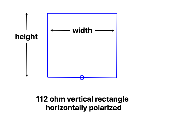
112 ohm rectangular loops
112 ohm loops match to 50 ohms using 1/4 wavelength of 75 ohm coax. Because they are shorter than the lower impedance loops, I’ve included dimensions down to 80m.
These loops are close to square, being only slightly wider than they are tall.
| Frequency MHz | Wire Length | Height | Width | 2 : 1 SWR Bandwidth MHz | 1.5 : 1 SWR Bandwidth MHz |
|---|---|---|---|---|---|
| 3.6 | 87 m (286 ft) | 21 m (69 ft) | 22.5 m (74 ft) | 0.16 | 0.09 |
| 5.35 | 58.2 m (190 ft) | 14.1 m (46 ft) | 15 m (49 ft) | 0.24 | 0.14 |
| 7.1 | 44 m (145 ft) | 10.8 m (35.4 ft) | 11.3 m (37 ft) | 0.33 | 0.18 |
| 10.1 | 31.2 m (102.4 ft) | 7.6 m (25 ft) | 8 m (26.2 ft) | 0.50 | 0.28 |
| 14.1 | 22.4 m (73.2 ft) | 5.44 m (17.8 ft) | 5.74 m (18.8 ft) | 0.70 | 0.40 |
| 18.1 | 17.44 m (57.2 ft) | 4.24 m (13.9 ft) | 44.8 m (14.7 ft) | 0.90 | 0.50 |
| 21.2 | 14.9 m (48.8 ft) | 3.6 m (11.8 ft) | 3.85 m (12.6 ft) | 1.10 | 0.65 |
| 24.9 | 12.72 m (41.8 ft) | 3.09 m (10.15 ft) | 3.27 m (10.75 ft) | 1.35 | 0.75 |
| 28.4 | 11.14 m (36.5 ft) | 2.7 m (8.85 ft) | 2.87 m (9.4 ft) | 1.55 | 0.87 |
| 50.5 | 6.28 m (20.6 ft) | 1.5 m (4.9 ft) | 1.64 m (5.4 ft) | 3.00 | 1.70 |
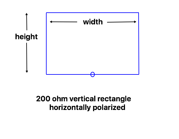
200 ohm rectangular loops
These dimensions for 200 ohm rectangular loops (fed at the bottom) are for a top height of 1/2 wavelength, as the flatter loops are more often used with a low top height. They have progressed beyond square to where the width is around 50% greater than the height.
They can be matched with a 4 : 1 balun, or using 1/4 wavelength of 100 ohm feedline. For American “zip cord”, which is typically 105 to 110 ohms, they should be stretched a bit wider and shorter, to give a feedpoint around 220 to 240 ohms.
| Frequency MHz | Wire Length | Width | Height | 2 : 1 SWR Bandwidth MHz | 1.5 : 1 SWR Bandwidth MHz |
|---|---|---|---|---|---|
| 1.85 | 168 m (550 ft) | 50 m (164 ft) | 34 m (111 ft) | 0.14 | 0.08 |
| 3.6 | 86 m (284 ft) | 26 m (85 ft) | 17 m (57 ft) | 0.29 | 0.16 |
| 5.35 | 58.4 m (191.4 ft) | 18 m (59 ft) | 11.2 m (36.7 ft) | 0.44 | 0.25 |
| 7.1 | 44 m (144.4 ft) | 13.2 m (43.3 ft) | 8.8 m (28.9 ft) | 0.62 | 0.36 |
| 10.1 | 31 m (101.6 ft) | 9.3 m (30.5 ft) | 6.2 m (20.3 ft) | 0.90 | 0.50 |
| 14.1 | 22.2 m (72.8 ft) | 6.6 m (21.6 ft) | 4.5 m (14.8 ft) | 1.30 | 0.75 |
| 18.1 | 17.3 m (56.8 ft) | 5.1 m (16.7 ft) | 3.55 m (11.7 ft) | 1.70 | 1.00 |
| 21.2 | 14.88 m (48.8 ft) | 4.44 m (14.6 ft) | 3 m (9.8 ft) | 2.00 | 1.20 |
| 24.9 | 12.64 m (41.4 ft) | 3.77 m (12.35 ft) | 2.55 m (8.35 ft) | 2.50 | 1.40 |
| 28.4 | 11.1 m (36.34 ft) | 3.25 m (10.67 ft) | 2.3 m (7.5 ft) | 2.80 | 1.60 |
| 50.5 | 6.16 m (20.2 ft) | 1.98 m (6.5 ft) | 1.1 m (3.6 ft) | 5.40 | 3.10 |
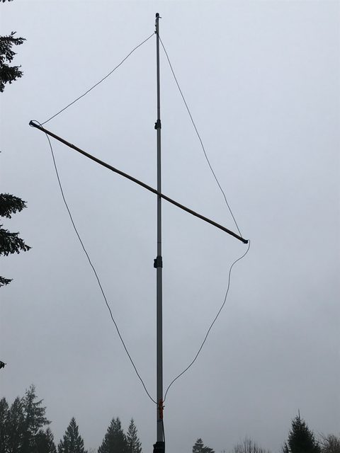
Data for horizontally polarized diamond loops
Diamond loops are the tallest of the shapes, and don’t make as good of a use of the available height as the other shapes. However, they can hang from a single high point, and often may be better when the top of the support is thin, such as a telescoping fishing rod. With a single top support, they can also be rotated more easily.
These dimensions are for loops made using 1 mm (AWG #18) bare wire, with the center of the loop at 1/2 wavelength above the ground, so they are relatively independent of height. They may require some adjustment if the bottom is close to the ground.
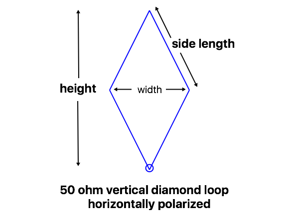
50 ohm diamond loops
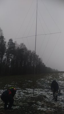
SQ1GU mounted 50 ohm loops for 3 bands on a single support.
These 50 ohm loops are convenient to hang from a fishing rod, tree branch, or other single support, with the sides tied off with ropes. Tying an extra string horizontally between the two side corners makes it easier to maintain the desired wire spacing: the length of that rope can be varied to adjust the impedance to 50 ohms. With the bottom near ground level, these can be used to connect directly to the radio without any feedline, which may make them attractive for backpacking or other portable operation where weight is important, although some adjustment to the loop length may be needed.
| Frequency MHz | Wire Length | Width | Height | Side Length | 2 : 1 SWR Bandwidth MHz | 1.5 : 1 SWR Bandwidth MHz |
|---|---|---|---|---|---|---|
| 7.1 | 44.5 m (146 ft) | 9.8 m (32 ft) | 20 m (65.6 ft) | 11.12 m (36.5 ft) | 0.145 | 0.085 |
| 10.1 | 31.4 m (101.5 ft) | 7 m (23 ft) | 14.04 m (46 ft) | 7.85 m (25.75 ft) | 0.21 | 0.13 |
| 14.1 | 22.6 m (74 ft) | 5 m (16.4 ft) | 10.1 m (33.1 ft) | 5.65 m (18.5 ft) | 0.32 | 0.18 |
| 18.1 | 17.6 m (57.6 ft) | 4 m (13 ft) | 7.82 m (26.7 ft) | 4.4 m (14.4 ft) | 0.42 | 0.24 |
| 21.2 | 15 m (49.5 ft) | 3.4 m (11.2 ft) | 6.7 m (22 ft) | 3.75 m (12.375 ft) | 0.50 | 0.37 |
| 24.9 | 12.8 m (42 ft) | 2.9 m (9.5 ft) | 5.7 m (18.7 ft) | 3.2 m (10.5 ft) | 0.60 | 0.34 |
| 28.4 | 11.6 m (37 ft) | 2.6 m (8.5 ft) | 4.98 m (16.3 ft) | 2.8 m (9.25 ft) | 0.65 | 0.40 |
| 50.5 | 6.4 m (20.8 ft) | 1.44 m (4.75 ft) | 2.83 m (9.3 ft) | 1.6 m (5.2 ft) | 1.30 | 0.75 |
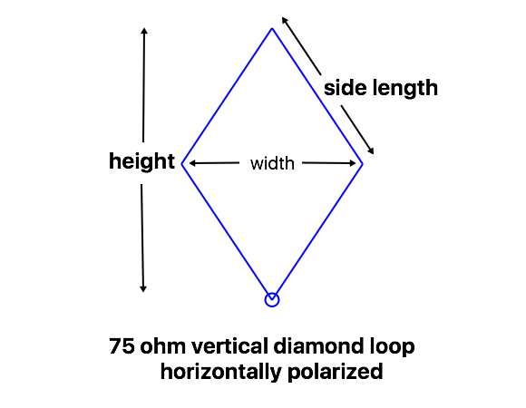
75 ohm diamond loops
The 75 ohm loops are a bit shorter and wider than the 50 ohm loops, but the total wire lengths are nearly the same, so one wire loop could be used for both, just by adjusting the center spacing (“width”). The SWR bandwidth is about 50% wider.
| Frequency MHz | Wire Length | Width | Height | Side Length | 2 : 1 SWR Bandwidth MHz | 1.5 : 1 SWR Bandwidth MHz |
|---|---|---|---|---|---|---|
| 7.1 | 44.4 m (145.6 ft) | 12.1 m (40 ft) | 18.6 m (61 ft) | 11.1 m (36.4 ft) | 0.22 | 0.12 |
| 10.1 | 31.2 m (102.6 ft) | 8.5 m (28 ft) | 13.1 m (43 ft) | 7.8 m (25.65 ft) | 0.31 | 0.18 |
| 14.1 | 22.5 m (74 ft) | 6.15 m (20.2 ft) | 9.4 m (30.8 ft) | 5.625 m (18.5 ft) | 0.46 | 0.27 |
| 18.1 | 17.52 m (57.6 ft) | 4.8 m (15.75 ft) | 7.32 m (24 ft) | 4.38 m (14.4 ft) | 0.60 | 0.35 |
| 21.2 | 15 m (49.2 ft) | 4.1 m (13.5 ft) | 6.28 m (20.6 ft) | 3.75 m (12.3 ft) | 0.75 | 0.40 |
| 24.9 | 13.6 m (42 ft) | 3.5 m (11.5 ft) | 5.35 m (17.5 ft) | 3.2 m (10.5 ft) | 0.90 | 0.55 |
| 28.4 | 11.4 m (36.6 ft) | 3.2 m (11 ft) | 4.58 m (15 ft) | 2.8 m (9.15 ft) | 1.00 | 0.60 |
| 50.5 | 6.32 m (20.8 ft) | 1.74 m (5.7 ft) | 2.64 m (8.65 ft) | 1.58 m (5.2 ft) | 1.90 | 1.10 |
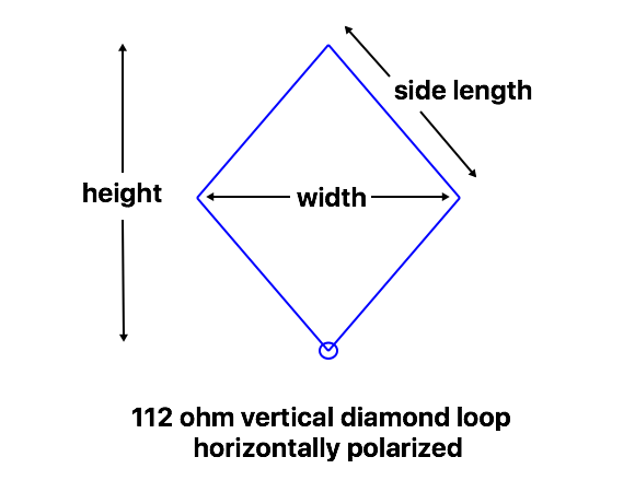
112 ohm diamond loops
These loops are almost square, and are designed to be matched with 1/4 wavelength of 75 ohm coax cable. SWR bandwidth is about 50% wider than the 75 ohm loops.
| Frequency MHz | Wire Length | Width | Height | Side Length | 2 : 1 SWR Bandwidth MHz | 1.5 : 1 SWR Bandwidth MHz |
|---|---|---|---|---|---|---|
| 3.6 | 87 m (286 ft) | 29 m (95 ft) | 32.5 m (107 ft) | 21.75 m (71.5 ft) | 0.15 | 0.09 |
| 7.1 | 44 m (145 ft) | 14.6 m (48 ft) | 16.6 m (54.5 ft) | 11 m (36.25 ft) | 0.33 | 0.19 |
| 10.1 | 31.2 m (102.4 ft) | 10.3 m (33.8 ft) | 11.7 m (38.4 ft) | 7.8 m (25.6 ft) | 0.53 | 0.28 |
| 14.1 | 22.4 m (73.5 ft) | 7.4 m (24.25 ft) | 8.4 m (27.5 ft) | 5.6 m (18.375 ft) | 0.70 | 0.40 |
| 18.1 | 17.5 m (57.36 ft) | 5.8 m (19 ft) | 6.54 m (21.5 ft) | 4.375 m (14.34 ft) | 0.95 | 0.55 |
| 21.2 | 15 m (49 ft) | 5 m (16.4 ft) | 5.55 m (18.2 ft) | 3.75 m (12.25 ft) | 1.10 | 0.65 |
| 24.9 | 12.8 m (42 ft) | 4.25 m (14 ft) | 4.75 m (15.5 ft) | 3.2 m (10.5 ft) | 1.30 | 0.75 |
| 28.4 | 11.2 m (36.8 ft) | 3.8 m (12.5 ft) | 4.1 m (13.5 ft) | 2.8 m (9.2 ft) | 1.50 | 0.90 |
| 50.5 | 4.7 m (20.68 ft) | 2.1 m (6.9 ft) | 2.35 m (7.71 ft) | 1.575 m (5.17 ft) | 3.00 | 1.70 |
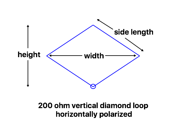
200 ohm diamond loops
These 200 ohm loops provide a wider SWR bandwidth than lower impedances: nearly 4 times that of the 50 ohm loops. For example, a 10m loop can cover nearly the whole band with an SWR 1.5 : 1 or better. They can be matched with a 4 : 1 balun or 1/4 wavelength of 100 ohm feedline.
| Frequency MHz | Wire Length | Width | Height | Side Length | 2 : 1 SWR Bandwidth MHz | 1.5 : 1 SWR Bandwidth MHz |
|---|---|---|---|---|---|---|
| 3.6 | 87 m (286 ft) | 36.5 m (120 ft) | 23.7 m (78 ft) | 21.75 m (71.5 ft) | 0.28 | 0.15 |
| 7.1 | 44 m (144.6 ft) | 18.5 m (60.7 ft) | 12 m (39.4 ft) | 11 m (36.15 ft) | 0.58 | 0.34 |
| 10.1 | 31 m (102 ft) | 13 m (42.65 ft) | 8.5 m (28 ft) | 7.75 m (25.5 ft) | 0.87 | 0.50 |
| 14.1 | 22.4 m (73.6 ft) | 9.35 m (30.7 ft) | 6.2 m (22.35 ft) | 5.6 m (18.4 ft) | 1.25 | 0.72 |
| 18.1 | 17.5 m (57.32 ft) | 7.3 m (24 ft) | 4.8 m (15.75 ft) | 4.375 m (14.33 ft) | 1.65 | 0.95 |
| 21.2 | 15 m (49 ft) | 6.3 m (20.67 ft) | 4 m (13.1 ft) | 3.75 m (12.25 ft) | 2.00 | 1.15 |
| 24.9 | 12.68 m (41.6 ft) | 5.35 m (17.55 ft) | 3.4 m (11.15 ft) | 3.17 m (10.4 ft) | 2.35 | 1.35 |
| 28.4 | 11.1 m (36.4 ft) | 4.85 m (15.9 ft) | 2.7 m (8.9 ft) | 2.775 m (9.1 ft) | 2.60 | 1.50 |
| 50.5 | 6.26 m (20.5 ft) | 2.66 m (8.72 ft) | 1.65 m (5.4 ft) | 1.565 m (5.125 ft) | 5.3 | 3.1 |
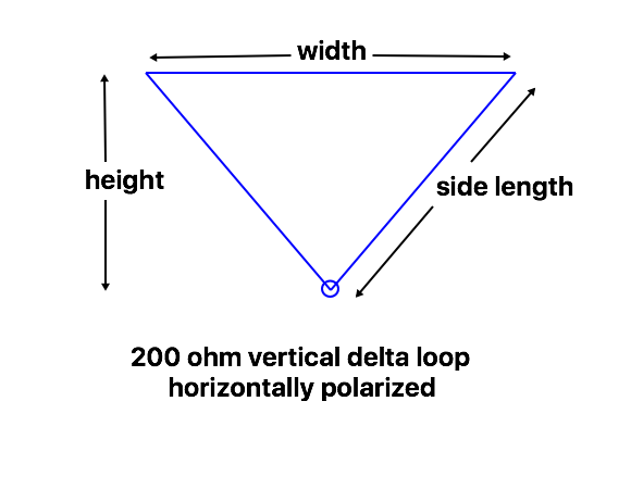
Data for horizontally polarized delta loops (point down)
The delta loops with the point down, fed in the bottom corner, can be strung between two trees like a dipole, with the advantage that the weight of the feedpoint and coax are pulling on angled wire rather than straight down in the middle. This reduces the sag in the top wire, which contributes the most to the radiation.
Because the delta loop shape is more effective at low heights, these loop dimensions are for a top height of around 1/2 wavelength. All are for 1 mm (AWG #18) bare wire. Impedance varies somewhat with height, but by adjusting the points where the ropes tie to the top of the loop, the shape is easy to adjust as needed.
Generally, loops fed in the center of the top wire, or inverted (so the point is up) will have similar dimensions for the listed impedances. Loops with the point down have a higher effective height for the same maximum height, but the single support loops at low heights work well for NVIS paths.
50 ohm delta loops
The 50 ohm loops are close to 1/2 wavelength tall, so the bottoms are relatively close to the ground. This makes them convenient for applications where it is desired to reduce (or eliminate) the weight and/or loss of the feedline. The width is about 1/4 wavelength, so they take less space than a half wave dipole.
As with the other 50 ohm loops, efficiency is improved by using larger wire. The use of 2 mm (AWG #12) wire raises the resonant frequency by about 0.5% for the same wire length.
Like other low impedance loops, bandwidth is relatively narrow – about half of the 7.0 – 7.3 MHz 40m band at 2 : 1 SWR.
| Frequency MHz | Wire Length | Width | Height | Side Length | 2 : 1 SWR Bandwidth MHz | 1.5 : 1 SWR Bandwidth MHz |
|---|---|---|---|---|---|---|
| 1.85 | 170 m (557 ft) | 40 m (131 ft) | 61.85 m (203 ft) | 65 m (213 ft) | 0.035 | 0.020 |
| 3.6 | 87.6 m (288 ft) | 20 m (66 ft) | 32.3 m (106 ft) | 33.8 m (111 ft) | 0.075 | 0.040 |
| 5.35 | 59.1 m (194.1 ft) | 13.5 m (44.3 ft) | 21.8 m (71.5 ft) | 22.8 m (74.9 ft) | 0.11 | 0.065 |
| 7.1 | 44.75 m (146.8 ft) | 10.5 m (34.45 ft) | 16.3 m (53.8 ft) | 17.125 m (56.2 ft) | 0.155 | 0.085 |
| 10.1 | 31.4 m (103.2 ft) | 7.2 m (23.6 ft) | 11.6 m (38 ft) | 12.1 m (39.8 ft) | 0.22 | 0.13 |
| 14.1 | 22.6 m (74.1 ft) | 5.2 m (17.1 ft) | 8.3 m (27.2ft) | 8.7 m (28.5 ft) | 0.33 | 0.19 |
| 18.1 | 17.6 m (57.9 ft) | 4 m (13.1 ft) | 6.52 m (21.6ft) | 6.8 m (22.4 ft) | 0.41 | 0.25 |
| 21.2 | 15 m (49.5 ft) | 3.5 m (11.5 ft) | 5.5 m (18 ft) | 5.75 m (19 ft) | 0.52 | 0.30 |
| 24.9 | 12.8 m (42.2 ft) | 3.0 m (9.8 ft) | 4.7 m (15.4 ft) | 4.9m (16.2 ft) | 0.63 | 0.36 |
| 28.4 | 11.25 m (36.9 ft) | 2.65 m (8.7 ft) | 4.1 m (13.4 ft) | 4.3 m (14.1 ft) | 0.72 | 0.42 |
| 50.5 | 6.4 m (20.9 ft) | 1.5 m (4.9 ft) | 2.325 m (7.6 ft) | 2.45 m (8.0 ft) | 1.40 | 0.80 |
75 ohm delta loops
The 75 ohm loops are a bit shorter and wider than the 50 ohm loops, with about 50% wider SWR bandwidth.
| Frequency MHz | Wire Length | Width | Height | Side Length | 2 : 1 SWR Bandwidth MHz | 1.5 : 1 SWR Bandwidth MHz |
|---|---|---|---|---|---|---|
| 1.85 | 170 m (558 ft) | 45 m (148 ft) | 61.5 m (191 ft) | 62.5 m (205 ft) | 0.05 | 0.03 |
| 3.6 | 87.5 m (287 ft) | 23.5 m (77 ft) | 30 m (98 ft) | 32 m (105 ft) | 0.11 | 0.06 |
| 5.35 | 59 m (193.5 ft) | 16 m (52.5 ft) | 20 m (65.5 ft) | 21.5 m (70.5 ft) | 0.16 | 0.095 |
| 7.1 | 44.6 m (146.2 ft) | 12 m (39.4 ft) | 15.2 m (50 ft) | 16.3 m (53.6 ft) | 0.23 | 0.13 |
| 10.1 | 31.5 m (103.5 ft) | 8.5 m (27.9 ft) | 10.7 m (35 ft) | 11.5 m (37.8 ft) | 0.34 | 0.20 |
| 14.1 | 22.6 m (74 ft) | 6.1 m (20 ft) | 7.65 m (25 ft) | 8.25 m (27 ft) | 0.50 | 0.30 |
| 18.1 | 17.6 m (57.7 ft) | 4.8 m (15.7 ft) | 5.95 m (19.5 ft) | 6.4 m (21 ft) | 0.65 | 0.37 |
| 21.2 | 15.1 m (49.5 ft) | 4.1 m (13.5 ft) | 5.1 m (16.7 ft) | 5.5 m (18 ft) | 0.75 | 0.45 |
| 24.9 | 12.9 m (42.3 ft) | 3.5 m (11.5 ft) | 4.35 m (14.3 ft) | 4.7 m (15.4 ft) | 0.90 | 0.55 |
| 28.4 | 11.3 m (37.2 ft) | 3.1 m (10.2 ft) | 3.8 m (12.5 ft) | 4.1 m (13.5 ft) | 1.00 | 0.60 |
| 50.5 | 6.39 m (21.0 ft) | 1.73 m (5.67 ft) | 2.16 m (7.1 ft) | 2.33 m (7.67 ft) | 2.00 | 1.20 |
112 ohm delta loops
The 112 ohm delta loops are close to equilateral, with the top just a little shorter than the sides. These are designed to match to 50 ohm using 1/4 wavelength of 75 ohm coax.
| Frequency MHz | Wire Length | Width | Height | Side Length | 2 : 1 SWR Bandwidth MHz | 1.5 : 1 SWR Bandwidth MHz |
|---|---|---|---|---|---|---|
| 1.85 | 170 m (558 ft) | 53 m (174 ft) | 52.2 m (171 ft) | 58.5 m (192 ft) | 0.075 | 0.045 |
| 3.6 | 87.6 m (287.5 ft) | 27 m (88.5 ft) | 27.15 m (89 ft) | 30.3 m (99.5 ft) | 0.155 | 0.09 |
| 5.35 | 59.2 m (192.1) | 18.8 m (61.7 ft) | 17.85 m (58.6 ft) | 20.2 m (66.2 ft) | 0.24 | 0.14 |
| 7.1 | 44.6 m (146.3 ft) | 14 m (45.9 ft) | 13.6 m (44.6 ft) | 15.3 m (50.2 ft) | 0.34 | 0.20 |
| 10.1 | 31.5 m (103.2 ft) | 10 m (32.8 ft) | 9.5 m (31.1 ft) | 10.75 m (35.2 ft) | 0.50 | 0.30 |
| 14.1 | 22.6 m (74.3 ft) | 7.1 m (23.3 ft) | 6.9 m (22.6 ft) | 7.75 m (25.5 ft) | 0.72 | 0.42 |
| 18.1 | 17.64 m (57.8 ft) | 5.5 m (18 ft) | 5.41 m (17.7 ft) | 6.07 m (19.9 ft) | 0.95 | 0.55 |
| 21.2 | 15.1 m (49.5 ft) | 4.74 m (15.5 ft) | 4.6 m (15.1 ft) | 5.18 m (17 ft) | 1.10 | 0.65 |
| 24.9 | 12.85 m (42.1 ft) | 4 m (13.1 ft) | 3.95 m (13 ft) | 4.425 m (14.5 ft) | 1.35 | 0.75 |
| 28.4 | 11.3 m (37 ft) | 3.6 m (11.1 ft) | 3.4 m (11.1 ft) | 3.85 m (12.6 ft) | 1.55 | 0.90 |
| 50.5 | 6.4 m (20.95 ft) | 2 m (6.55 ft) | 1.95 m (6.4 ft) | 2.2 m (7.2 ft) | 3.00 | 1.70 |
200 ohm delta loops
The 200 ohm loops are nearly as wide as a dipole, but with a wider SWR bandwidth: less than 1.5 : 1 from 7.0 to 7.3 MHz. The shape is close to a right triangle, with the right angle at the bottom. I use this design for my 40m portable loop antennas, because the wider bandwidth maintains a good match in spite of variations in how it is installed in the trees. Some “as built” dimensions for 40m loops using insulated wire are on the 200 ohm Portable Loop page.
| Frequency MHz | Wire Length | Width | Height | Side Length | 2 : 1 SWR Bandwidth MHz | 1.5 : 1 SWR Bandwidth MHz |
|---|---|---|---|---|---|---|
| 1.85 | 170 m (556 ft) | 66 m (216 ft) | 40 m (131 ft) | 52 m (170 ft) | 0.13 | 0.075 |
| 3.6 | 87.2 m (286 ft) | 34 m (112 ft) | 20.5 m (67 ft) | 26.6 m (87 ft) | 0.27 | 0.16 |
| 5.35 | 59 m (193 ft) | 23.5 m (77 ft) | 13.2 m (43 ft) | 17.75 m (58 ft) | 0.40 | 0.25 |
| 7.1 | 44.4 m (145.5 ft) | 17.2 m (56.5 ft) | 10.5 m (34.5 ft) | 13.6 m (44.5 ft) | 0.56 | 0.34 |
| 10.1 | 31.3 m (103 ft) | 12.1 m (39.7 ft) | 7.5 m (24.5 ft) | 9.6 m (31.6 ft) | 0.85 | 0.50 |
| 14.1 | 22.5 m (73.5 ft) | 8.7 m (28.5 ft) | 5.33 m (17.5 ft) | 6.9 m (22.5 ft) | 1.25 | 0.70 |
| 18.1 | 17.5 m (57.5 ft) | 6.8 m (22.3 ft) | 4.15 m (13.5 ft) | 5.35 m (17.6 ft) | 1.60 | 0.95 |
| 21.2 | 14.95 m (49.2 ft) | 5.85 m (19.2 ft) | 3.5 m (11.5 ft) | 4.55 m (15 ft) | 2.00 | 1.10 |
| 24.9 | 12.8 m (42 ft) | 5 m (16.4 ft) | 3 m (9.8 ft) | 3.9 m (12.8 ft) | 2.30 | 1.35 |
| 28.4 | 11.22 m (36.75 ft) | 4.5 m (14.75 ft) | 2.5 m (8.2 ft) | 3.36 m (11 ft) | 2.60 | 1.50 |
| 50.5 | 6.3 m (20.7 ft) | 2.5 m (8.2 ft) | 1.45 m (4.8 ft) | 1.9 m (6.25 ft) | 5.0 | 3.0 |
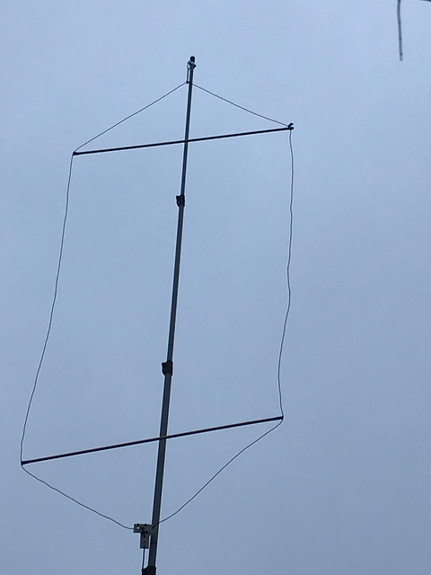
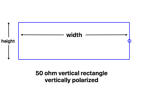
Data for vertically polarized rectangular loops
These vertically polarized loops are most often used on the lower bands to achieve low angle polarization. For that reason, dimensions are only given through 20m, but they can be scaled to other bands if desired. Note that the bottom wire is set at 3 m (10 feet) off the ground (considered a safe height to avoid human contact with the wire): because this isn’t defined as a function of wavelength, the dimensions don’t scale exactly, and the dimensions are strongly affected by the capacitive coupling between the center of the bottom wire (a point of high impedance) and the ground below it.
The center of the bottom wire is a high impedance point, and coupling between that and ground will change the required loop dimensions when the loop is installed at lower heights. Lowering the loop will decrease the gain and increase the feedpoint impedance (both due to ground losses), and lower the resonant frequency of the antenna. For reference, lowering the bottom of the 20m 50 ohm delta loop from 3m to 1m above ground decreased the gain by about 1 dB, raised the feedpoint impedance at resonance to 69 ohms, and shifted the resonant frequency down about 100 kHz. The loop is still usable at the lower height, but expect to shorten the wire a bit and flatten the antenna a bit when installed at lower heights.
Because height is often a limitation, dimensions are only given for 50 and 75 ohm rectangular loops, which are suitable for direct coax feed. Further discussion of the characteristics of these loops is in the theory article.
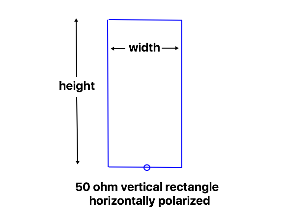
50 ohm rectangular loops
These vertically polarized 50 ohm rectangles have different dimensions than the horizontally polarized rectangles given previously, due to the effect of the ground. Rather than a 2 : 1 ratio of width to height, it is over 4 : 1 on 160m, down to about 2.5 : 1 on 20m, with the bottom wire at 3 m (10 feet) off the ground. There will also be some variation due to ground conditions, so expect to make some adjustments if a precise 50 ohm match is important.
These models are for 1 mm (AWG #18) bare wire. As with the other 50 ohm loops, thicker wire may be a good idea, especially on the lower bands.
| Frequency MHz | Wire Length | Width | Height | 2 : 1 SWR Bandwidth MHz | 1.5 : 1 SWR Bandwidth MHz |
|---|---|---|---|---|---|
| 1.85 | 163 m (534 ft) | 67 m (220 ft) | 14.5 m (47 ft) | 0.035 | 0.020 |
| 3.6 | 84.8 m (278 ft) | 33.4 m (109.5 ft) | 9 m (29.5 ft) | 0.070 | 0.040 |
| 5.35 | 57.4 m (188 ft) | 22 m (72 ft) | 6.7 m (22 ft) | 0.110 | 0.065 |
| 7.1 | 43.5 m (143 ft) | 16.25 m (53.5 ft) | 5.5 m (18 ft) | 0.16 | 0.09 |
| 10.1 | 30.8 m (100.9 ft) | 11.2 m (36.75 ft) | 4.2 m (13.7 ft) | 0.22 | 0.13 |
| 14.1 | 22.1 m (68.6 ft) | 7.86 m (23.8 ft) | 3.2 m (10.5 ft) | 0.32 | 0.18 |
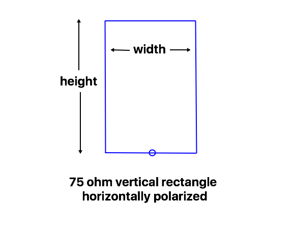
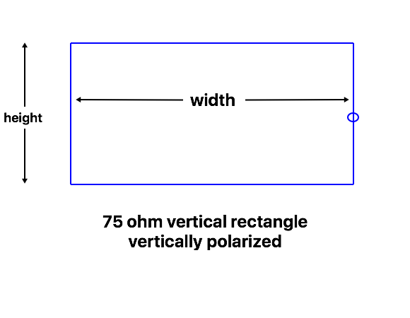
75 ohm rectangular loops
These 75 ohm loops also have different dimensions from the horizontally polarized antennas due to the interaction with the ground.
| Frequency MHz | Wire Length | Width | Height | 2 : 1 SWR Bandwidth MHz | 1.5 : 1 SWR Bandwidth MHz |
|---|---|---|---|---|---|
| 1.85 | 163.6 m (536.5 ft) | 61.8 m (202.75 ft) | 20 m (65.5 ft) | 0.055 | 0.030 |
| 3.6 | 85 m (278.8 ft) | 31 m (101.7 ft) | 11.5 m (37.7 ft) | 0.105 | 0.60 |
| 5.35 | 57.8 m (190 ft) | 20.4 m (67 ft) | 8.5 m (27.9 ft) | 0.160 | 0.095 |
| 7.1 | 43.74 m (143.6 ft) | 15.07 m (49.5 ft) | 6.8 m (22.3 ft) | 0.22 | 0.13 |
| 10.1 | 31 m (101.6 ft) | 10.25 m (33.6 ft) | 5.25 m (17.2 ft) | 0.33 | 0.19 |
| 14.1 | 22.39 m (73.2 ft) | 7.2 m (23.6 ft) | 3.95 m (13 ft) | 0.47 | 0.27 |
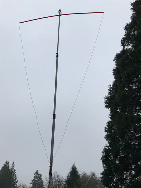
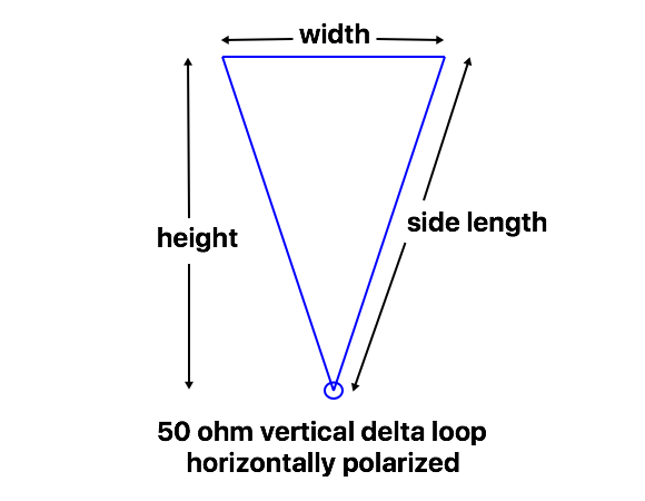
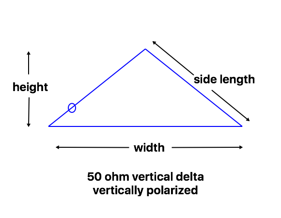
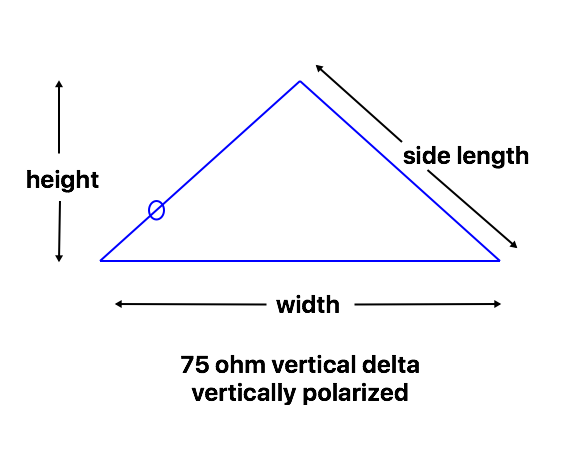
Data for vertically polarized delta loops
Delta loops with the point upwards are probably the most common vertically polarized loop, as only one high support is needed. Dimensions are given here for 50, 75, and 112 ohm versions.
In these models, the bottom wire is fixed at 3 m (10 ft) above ground, to reduce the chance of human contact with the high impedance point in the center of the bottom wire. As with the rectangles, this fixed height means that the dimensions don’t necessarily scale with frequency, especially on the lower bands.
Dimensions are only given up through 20m, because that will be the most common usage, but the highest frequency design can be scaled as a starting point for higher bands if desired.
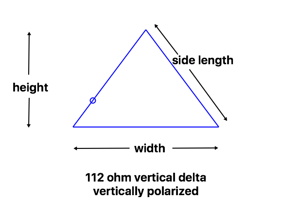
The feedpoint for vertical polarization of the delta loops is 1/4 of the Wire Length down one side from the top corner. This puts it close to, but somewhat above, a bottom corner.
50 ohm delta loops
These 50 ohm loops are strongly affected by ground, which has the effect of reducing the required mast height to less than 1/4 wavelength on the lower bands. Bandwidth is a bit wider than for the horizontally polarized loops due to ground losses. Probably the easiest way to adjust them is to raise the wire to the top of the mast, then adjust the total wire length and the positions of the lower corners for a good match at the desired center frequency.
| Frequency MHz | Wire Length | Width | Height | Side Length | 2 : 1 SWR Bandwidth MHz | 1.5 : 1 SWR Bandwidth MHz |
|---|---|---|---|---|---|---|
| 1.85 | 168 m (552 ft) | 78.8 m (258.6 ft) | 21 m (68.9 ft) | 44.65 m (146.5 ft) | 0.035 | 0.021 |
| 3.6 | 87.5 m (285 ft) | 40.2 m (130 ft) | 12.45 m (40.8 ft) | 23.65 m (77.5 ft) | 0.075 | 0.045 |
| 5.35 | 59.1 m (194 ft) | 26.7 m (87.6 ft) | 9.2 m (30.2 ft) | 16.2 m (53.2 ft) | 0.12 | 0.07 |
| 7.1 | 44.7 m (146.6 ft) | 20 m (65.6 ft) | 7.25 m (23.75 ft) | 12.35 m (40.5 ft) | 0.15 | 0.09 |
| 10.1 | 31.6 m (103.75 ft) | 13.8 m (45.34 ft) | 5.6 m (18.4 ft) | 8.9 m (29.2 ft) | 0.23 | 0.13 |
| 14.1 | 22.76 m (74.5 ft) | 9.76 m (32 ft) | 4.25 m (14 ft) | 6.5 m (21.25 ft) | 0.33 | 0.19 |
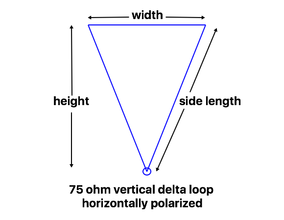
75 ohm delta loops
The 75 ohm loops are a bit taller and narrower than the 50 ohm loops, with a wider SWR bandwidth. Wire lengths and distance from the top corner to the feedpoint position remain about the same.
| Frequency MHz | Wire Length | Width | Height | Side Length | 2 : 1 SWR Bandwidth MHz | 1.5 : 1 SWR Bandwidth MHz |
|---|---|---|---|---|---|---|
| 1.85 | 167 m (548 ft) | 74.5 m (244 ft) | 27.5 m (90.2 ft) | 46.3 m (151.9 ft) | 0.055 | 0.030 |
| 3.6 | 87.2 m (286 ft) | 37.9 m (124.3 ft) | 15.75 m (51.65 ft) | 24.64 m (80.85 ft) | 0.110 | 0.065 |
| 5.35 | 59 m (193.5 ft) | 25 m (82 ft) | 11.5 m (37.7 ft) | 17 m (55.75 ft) | 0.17 | 0.10 |
| 7.1 | 44.7 m (146.6 ft) | 18.7 m (61.4 ft) | 9 m (29.5 ft) | 13 m (42.6 ft) | 0.23 | 0.13 |
| 10.1 | 31.5 m (103.3 ft) | 12.9 m (42.3 ft) | 6.7 m (22 ft) | 9.3 m (30.5 ft) | 0.32 | 0.20 |
| 14.1 | 22.7 m (74.5 ft) | 9 m (29.5 ft) | 5.15 m (16.9 ft) | 6.85 m (22.5 ft) | 0.50 | 0.29 |
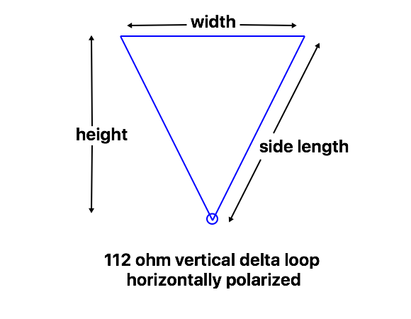
112 ohm delta loops
The 112 ohm loops require a taller support, but provide a wider SWR bandwidth than the lower impedance designs. They match to 50 ohms with a 1/4 wavelength of 75 ohm coax.
| Frequency MHz | Wire Length | Width | Height | Side Length | 2 : 1 SWR Bandwidth MHz | 1.5 : 1 SWR Bandwidth MHz |
|---|---|---|---|---|---|---|
| 1.85 | 167 m (546 ft) | 69 m (226 ft) | 34.5 m (113 ft) | 49 m (160 ft) | 0.080 | 0.045 |
| 3.6 | 86.6 m (284.5 ft) | 34.6 m (113.5 ft) | 19.5 m (64 ft) | 26 m (85.5 ft) | 0.17 | 0.10 |
| 5.35 | 59 m (193 ft) | 22.75 m (74.5 ft) | 14 m (46 ft) | 18 m (59 ft) | 0.28 | 0.15 |
| 7.1 | 44.5 m (145.8 ft) | 16.8 m (55 ft) | 11 m (35 ft) | 13.85 m (45.4 ft) | 0.35 | 0.20 |
| 10.1 | 31.5 m (103.4 ft) | 11.7 m (38.4 ft) | 8 m (26.2 ft) | 9.9 m (32.5 ft) | 0.50 | 0.29 |
| 14.1 | 22.6 m (74 ft) | 8 m (26.25 ft) | 6.1 m (20 ft) | 7.3 m (23.9 ft) | 0.74 | 0.44 |
back to:
construction of wire loop antennas
related links
vertically polarized delta loop video
5-element 20m portable delta loop beam