multiband dipoles
last updated 11 December 2024.
The half-wave dipole is primarily a monoband antenna, since it is one-half wavelength long at only one frequency.
But because it is such a simple and effective antenna for many HF applications, several different methods have been developed to use a single dipole antenna on 2 or more bands. We can group them as follows:
- harmonic resonances
- multiple dipoles on a common feedpoint
- tuned antennas (“doublets“)
- the original fan dipole
- trap dipoles
- off-center or end feeding
- changing the effective dipole length
harmonic resonances
A dipole will present a low feedpoint impedance when each leg is close to an odd multiple of 1/4 wavelength. This is commonly used to operate 15m using a 40m dipole, or 10m using the 7th harmonic resonance with an 80m dipole. This was more convenient with tube transmitters that could tolerate a higher SWR, however. A dipole resonant at 7.15 MHz has a 3rd harmonic resonance around 21.7 MHz, where the impedance is about 105 ohms. At 21.3 MHz the SWR is about 2.6 : 1, and over 4 : 1 at the bottom of the 15m band. Adding a 35cm (14 inch) hanging wire about 3m (10 ft) out from the feedpoint on both sides should bring the resonance closer to the 15m band (this provides capacitive loading at a high impedance point on 15m, with little change on 40m).
A half-wave dipole for 4 MHz will have a 7th order resonance around 28.3 MHz, with a feedpoint impedance around 135 ohms.
The higher resonances will also result in more lobes and nulls in the radiation pattern. For antennas installed as an inverted vee, the slope of the wires can degrade the pattern on the higher resonances.
So while it certainly can work, it does need some attention to detail to ensure that it works well for your particular application.
multiple dipoles on a common feedpoint
This is one of the simplest arrangements, at least for a limited number of bands. Two or more dipole antennas a connected to a common feedline. As long as the frequencies and the antenna wires are far enough apart, they will work independently.
When the wires are close together, there will be more interaction in the tuning. This has been done using multi-conductor cable, and cutting each wire for a different frequency, but expect to do a lot of adjustment to get it to work. Letting the ends of the wires hang down from the bundle will help, as the wire ends seem to be most susceptible to detuning. When using separate wires, tying each off to a different anchor point, or at least letting one hang down below the other, reduces the interaction.
I’ve used this approach for my portable dipole kits for decades on the traditional (pre-WARC) HF bands, where each individual dipole will have a high impedance on most other bands. There is more interaction with closer spacing of frequencies, and trying to cover 20m, 17m, 15m, 12m, and 10m using this method may not work very well. I’ve also used it in conjunction with my dual-band dipole design: a 20 + 80m element along with a 40m element that also covers 15m makes a simple Field Day antenna for 4 bands, and the elements can be used to guy the center support.
This is sometimes called “fan dipole”, even when the antenna wires aren’t arranged in the shape of a fan. But I use that name instead for the original fan dipole.
tuned antennas (“doublet”)
A “doublet” is a generic term for a dipole that is fed with low loss cable (typically parallel-conductor twinlead or open wire line with impedances of 300 – 600 ohms) and matched on multiple bands using an antenna tuner at the junction between the parallel-conductor line and the coax.
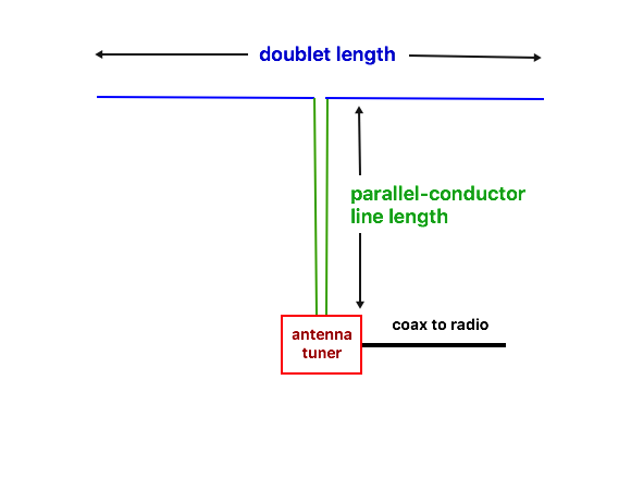
It is common for such antennas to be dimensioned as a half wave on the lowest band of operation, but this often ensures that the feedpoint impedance will be high on other bands. Usually they can be matched with a good wide-range antenna tuner: the impedance that the tuner sees will depend on the lengths of the antenna and the feedline, and can vary over a very wide range. If these are outside the available matching range of the tuner, then extra lengths of line can be added on the output of the tuner to change the impedance so it is easier to match. In practice, it may be easier to start with an antenna length that isn’t resonant: the exact length makes little difference when a tuner is used.
My experience using a 40m doublet on 40m, 20m, and 15m, is that sometimes, depending on the line length, I couldn’t get a good match on 20m with any of my tuners, but other times I could (when I happened to use a different feedline length).
The practical minimum length is often stated as 3/8 wavelength, as efficiency can drop below that point. Shorter lengths can be pressed into service, but the matching range of (and potential losses in) the tuner should be evaluated. At least keep an eye on the temperature of the coil in the tuner to make sure it doesn’t overheat.
DJ0IP has a good summary of results with various doublet lengths.
There have been some combinations of antenna and feedline lengths that have been recommended for use without a tuner on some bands over the years. Perhaps the best known is the G5RV antenna developed in the 1940’s and 50’s. This consists of a horizontal antenna 31m (102 ft) long, fed in the middle with 8.5m to 10.5m (28 to 34 ft) of parallel conductor line (depending on the velocity factor of the line used). The basic antenna is 3/2 wavelengths on 20m, giving a 6-lobed radiation pattern, and the balanced line should be 1/2 electrical wavelength on 20m, although G5RV noted that it often worked better to bring the balanced line all the way to a tuner in the shack rather than making the transition to coax (which might have been 80 ohms in that era). While this arrangement could often be fed directly from tube (valve) transmitters of the time, the SWR is often too high for modern solid state transmitters and 50 ohm coax, so the use of an antenna tuner is strongly recommended, and coax losses may be high on some bands.
Owen Duffy, VK2OMD, has excellent articles on Feeding a G5RV and Optimizing a G5RV.
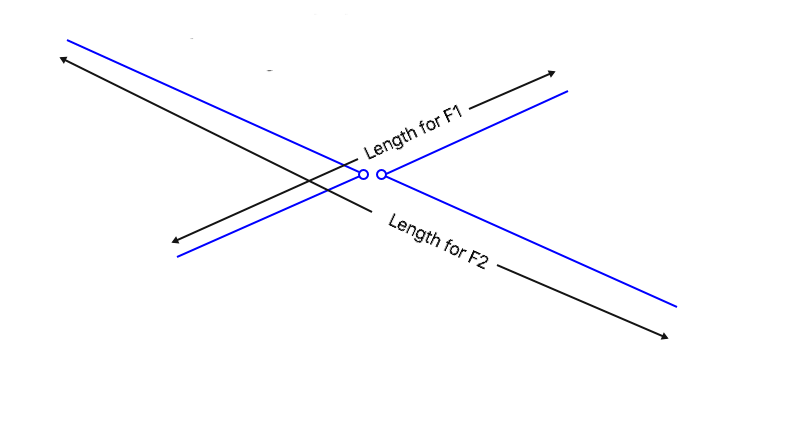
Brian Austin, G0GSF / ZS6BKW, ran a computer optimization to find a combination of lengths that would allow the maximum number of HF bands where the SWR is less than 2 : 1 for modern transmitters. The result is the “ZS6BKW” antenna, with slightly different dimensions from the original G5RV. The top wire was reduced to 27.9m ( 91.5 ft) and the matching line (which must have a characteristic impedance of 400 ohms) was lengthened to 13.6m ( 44.6 ft ) multiplied by the velocity factor. This gives an SWR under 2 : 1 on the following bands: 40m, 20m, 17m, 12m, and 10m, although it may require a bit of optimization.
More details on the G5RV and ZS6BKW, from the late W4RNL.
original fan dipole
The original fan dipole and related antennas modify the shape of the elements to cover a wide frequency range, like 5 to 30 MHz or more, with a reasonably low SWR.
trap dipoles
A “trap” is a parallel-tuned circuit consisting of a coil and a capacitor. The circuit presents at high impedance at the resonant frequency. Inserting traps into a dipole element make it appear to be different lengths on two different frequencies.
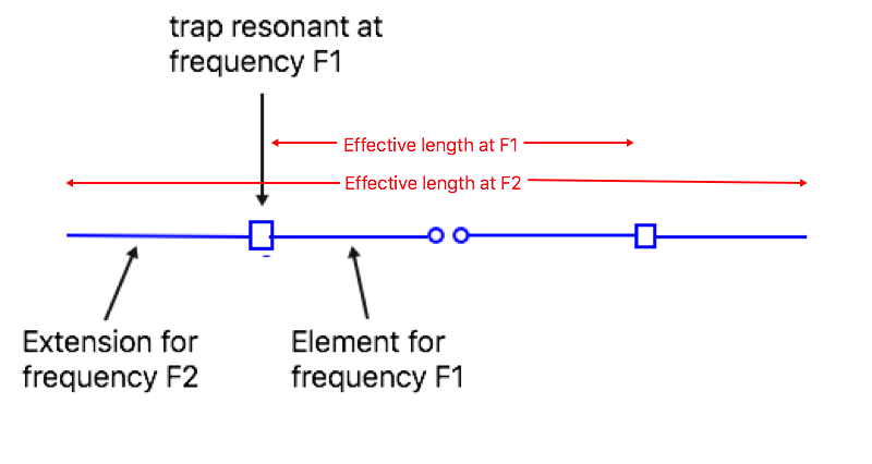
In this simple case, the trap is resonant at frequency F1, and the distance from the feedpoint to the trap is set for that frequency. The trap blocks the RF at F1 from continuing out the wire, making the center portion of the antenna operate as a half wavelength on F1. The wire extends beyond the trap far enough to make it resonant on a lower frequency F2, where it also operates as a half wave dipole.
In practice it is more complex than this: the trap adds some inductance to the antenna at F2, so the extension wire is shorter than it would be otherwise, and the SWR bandwidth of the antenna will be narrower. More traps can be added, and it can be an effective way to have a single antenna operate on multiple bands.
My dual frequency dipole is effectively a trap antenna, but relying on a large coil rather than a trap with an explicit capacitor.
You often hear about how bad the losses are in a trap. Actually, they needn’t be as bad as often reported. Losses are highest when the trap is resonant at the operating frequency, but it can be tuned a bit off frequency and still work well.
In general, the design of a trap dipole for two frequencies comes down to solving two equations (for the two resonant frequencies) with 4 variables (the two wire lengths, and the capacitance and inductance used in the trap), so there are many combinations that will work. Any two can be fixed ahead of time over a “reasonable” range, and the other two calculated accordingly. As the design diverges more from the “traditional” approach, however, there is more interaction in tuning the antenna to the two desired frequencies, and the feedpoint impedance may increase, making the SWR worse.
There can be high voltage across the trap components, even at moderate power, and common capacitors may not survive if they are not rated for high voltage. A common alternative is to wind the trap using coax cable, with the outside of the cable acting as the coil in parallel with the capacitance between the center conductor and the shield. Note that many such calculators don’t treat the coax as a transmission line, resulting in the resonant frequency being too low. In practice, the trap is simply tuned by shortening the coax until it is resonant at the desired frequency, or is used as is, and the wire lengths are adjusted as needed.
off-center or end feeding.
I grouped these two together here because the radiation patterns and some of the issues are similar.
The principle is that the feedpoint impedance varies along the antenna when it is fed off-center, and in some cases this can be arranged to give a reasonable match on several bands. In most cases, the bands must be integer multiples of the fundamental resonant frequency, although some designs use loading coils or other methods of shifting the resonances. For example, a 40m antenna may be usable on 20m, 15m, and 10m, while an 80m antenna may be usable on many of the bands above 7 MHz, even if the resonances don’t line up exactly with the band edges.
The Off-Center Fed Dipole (OCFD) places the feedpoint typically between 20% and 40% of the way in from one end: the feedpoint position determines which bands the antenna will match without a tuner (and trying to use a tuner to match the other bands may lead to failure of the balun). Feedpoint impedances are often in the 200 – 400 ohm range, and a balun is designed to match to coax.
The End-Fed Half-Wave antenna is fed at one end, where the impedance is high. Typical values are 2000 – 5000 ohms. This can be matched in several ways: with an L network tuner, with a parallel-tuned circuit, a quarter wave matching stub, or with a wide-band ferrite transformer.
Both types are subject to strong common mode current. Older designs for voltage baluns or air-core common mode chokes are often inadequate.
While any straight half-wave wire will have the same radiation pattern regardless of where it is fed, there are significant differences on harmonic frequencies. An 80m dipole / doublet used on 40m will have maximum radiation straight up, useful for NVIS coverage, while the same length of wire fed as an OCFD or EFHW will have a null broadside to the antenna (including straight up), and maximum radiation at an angle of about 50 degrees from the ends of the wire. At higher frequencies, the maximum radiation will be even closer to the ends of the wire, and this can reduce performance when the antenna is installed as an inverted vee.
changing the antenna length
There are two common ways to do this, and it can be automated or manual.
The simplest from the perspective of home construction is often known as a link dipole. The wire is broken into segments that can be joined with wire links or switches to select different bands.
unconventional link dipole for 20/30/40m
There are many ways to implement this idea. It simply requires some sort of insulator between the sections of wire, and some way to connect the wires. I like to use Anderson Connectors for larger versions (the insulator takes the stress, so the connectors don’t pull apart due to tension on the wire).
The second method is to wind up the portion of the antenna that isn’t needed for resonance. This is used commercially in the Stepper antennas, and there several methods that are easier to build at home. For example, G8JNJ’s “Fat Max” vertical uses a tape measure. Plastic washing line reels or chalk line holders can be used to roll up each end of the dipole to the required length. This is sometimes called a “reel dipole”.
Note that there is a difference in the effective wire length, depending on whether the wire is insulated or bare. But generally the setting for each band will need to be found experimentally, then the wire can be marked to make it easier to find the right spot when changing bands. (Different colors of tape or heat shrink tubing may be useful for this.)
This approach is particularly useful when the antenna may need to be used on a wide range of frequencies, as it can be set to any length up to the maximum wire length in the reel. In that case, marking the wire every 1 MHz or 500 kHz may make it easier to locate a particular frequency, rather than marks for each ham band.
Both of these approaches require that the antenna be manually adjusted when changing bands. That isn’t always convenient at night or in the middle of a storm, but these antennas may be a useful backup when operating with other services using different HF frequencies.