A Link Dipole
last updated 30 November 2024.
A “link dipole” (or “linked dipole”) is a simple way to permit one antenna to be used on multiple bands. A wire dipole for the lowest band is broken up with insulating joints, then the joints can be opened or shorted (“linked”) to operate on any of the bands.
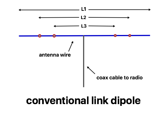
In the drawing above, the lowest operating frequency is set by the overall length L1. The red circles represent link points where the ends of the wire can be opened or shorted together. Opening the two outermost links reduces the wire length to L2, to operate on a higher band. The inner most links are opened to operate on the highest band, corresponding to L3. This can be extended to cover many different bands. Because manual intervention is required to change bands, this is most commonly used for portable or temporary operation, where the antenna is reasonably accessible and band changes are not too frequent. Standard dipole dimensions can be used, and a calculator is available, although some adjustment may be required due to the construction details of the links.
Of course, the dipole can be installed as an inverted vee or other shapes, just like a normal wire dipole.
advantages
Minimizes the total amount of wire required to get a low SWR on multiple bands without a tuner, especially for closely-spaced combinations such as 20 / 17 / 15 / 12 / 10 m.
Resonant frequency for each band can be adjusted individually.
Can be built for any combination of bands.
disadvantages
Requires manual changes to the antenna, often including lowering it and raising it back up again, to switch bands.
practical application
While the principle is simple, there are some practical details that make the antenna much easier to use in the field.
- The antenna is not disassembled when the links are disconnected. The unused wires simply act as extension ropes on the ends. I like to provide an option to disconnect the unused wires when required in a specific circumstance, but generally the antenna is kept as a single unit. That means that changing the band settings does not change the required lengths of the end ropes, giving an extra time savings when changing bands.
- The antenna needs to be lowered to change bands (unless it is installed at a low height). The simplest method is to lower the center, change the link settings, and raise it back up. Untying the end ropes to lower each side individually won’t work on the higher bands when the center is too high, as the links may still be out of reach of the ground.
- Especially when built for multiple bands, some sort of marking or color coding on each link point to identify the associated band helps to reduce mistakes.
- To operate on a lower frequency than the overall length, loading coils can be added across open links. For example, a link dipole for 40m and 20m can be used on 80m by adding loading coils across the 20m link point.
link construction
The basic requirements for each link point are:
- Provide the ability to open or close the link fairly easily.
- Provide mechanical strength for the antenna whether the link is open or closed.
Optional requirements may include:
- Provide the ability to disconnect the unused wire from the antenna if needed.
- Provide the ability to add a loading coil across the link.
- Provide some capability to adjust the resonant frequency in the field.
- Not require any special tools, or loose parts that can be lost in the field.
There are two basic functions that each link needs to provide. One is the connection, and the other is strain relief, so there is no mechanical stress on the electrical connection (and to reduce breakage from wires flexing at joints). I use the same methods as I do for wire dipole construction.
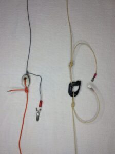
This photo shows two common methods for the links. In each the wires are tied to an insulator for strain relief, and the ends have some sort of connectors. The details are very much a matter of personal preference and what materials are available. The alligator clip used on the left can also be clipped onto the grey wire to adjust the tuning of the higher band if it is on the feedpoint side of the link. (My experience with inexpensive alligator clips is that they quickly rust in wet weather, such as we often have here in Oregon, and the contacts may become intermittent.) Using different colors of wire for each section is a useful method of identify which is which. The automotive blade connectors on the right may need to be loosened a bit: I have sometimes pulled the wires out of the connectors when trying to separate them. The insulator used on the right is sold for electric fences, and opens like a carabiner to separate the antenna there if needed.
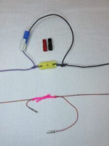
Anderson Power Poles are another common connector. Besides the common red and black pairs, the plastic shells are available different colors (white and blue in this example). That permits color-coding your connections, making it easier to write instructions for others to use the antenna (“for 15m, mate the yellow and green connectors”).
The lower link in the photo is about the smallest and lightest version that I have come up with so far. The insulator is a sort piece of thin rope tied between the two wire ends, so the antenna rolls up easily. The connectors are the pins used in plastic-bodied multi-pin connectors, which can be purchased separately. They probably will need some anti-corrosive paste on the contact surfaces to survive long out in the weather. In this case, the wire is stranded, insulated 0.4 mm (AWG #26) hookup wire, which will make a very light antenna for backpacking.
Notice that I leave a relatively long “tail” on the side of the link closest to the feedpoint. The tuning of a wire antenna will vary depending on how the wire is folded or tied, so I tie the wire to the insulator before I start tuning it up. Once it is tuned, retying it may shift the tuning, so I just allow plenty of extra on the end and don’t bother trying to tie it off shorter once I have it tuned. This longer end can also be wrapped around the antenna wire in various ways to adjust the tuning in the field if needed. If you cut the wire too short during tuning, there is no problem with splicing some extra back on, as there is no mechanical strain on the wire at this point. You can also use the connectors to add short extension wires, for example, to shift an antenna tuned for the upper part of the band down the CW or digital segments, or even to a lower band not covered by the original antenna.
an unconventional link dipole
Some years ago I made a conventional link dipole for 40m and 80m, and discovered that, with one link open and one shorted, it resonated close to 60m. One reason for that is because a dipole can be fed a reasonable amount off center before the SWR increases too much. Following that thought lead to this unconventional link dipole, which requires fewer links, but a better balun:
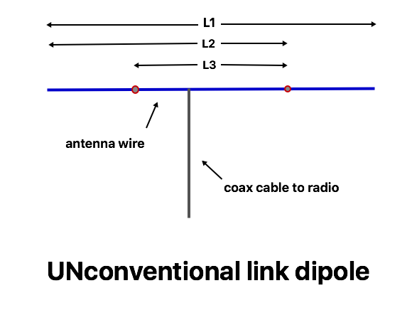
We end up with just one link per band, rather than two. The feedpoint resistance increases, because the antenna is now fed off-center, but not too much: either 50 or 75 ohm coax can be used.
Let’s compare some sample dimensions for the two link dipoles, assuming we want to cover all 7 ham bands 40m through 10m. These are modeled numbers for 1 mm (AWG #18) wire, and actual lengths will need some correction for knots, etc.
| band | conventional total wire length each side meters ( feet ) | UNconventional total wire length left side meters ( feet ) | UNconventional total wire length right side meters ( feet ) |
|---|---|---|---|
| 10m | 2.6 m ( 8.5 ft ) | 2.3 m ( 7.5 ft ) | 2.8 m ( 9 ft ) |
| 12m | 2.9 m ( 9.6 ft ) | 3.2 m ( 10.4 ft ) | |
| 15m | 3.5 m ( 11.4 ft ) | 3.8 m ( 12.5 ft ) | |
| 17m | 4.1 m ( 13.3 ft ) | 4.3 m ( 14.2 ft ) | |
| 20m | 5.2 m ( 17.2 ft ) | 6 m ( 17.2 ft ) | |
| 30m | 7.3 m ( 24 ft ) | 8.5 m ( 28 ft ) | |
| 40m | 10.3 m ( 33.8 ft ) | 11.9 m ( 39 ft ) |
The blank cells in the table are to emphasize that the wire length on that side of the antenna doesn’t change from the prior band. As a result, there are a total of 6 links required in the unconventional version, compared to 12 in the original.
In my model, at any rate, when the antenna is set as an inverted vee with a feedpoint impedance close to 50 ohms, the highest deviation that I saw was around 60 to 65 ohms – still an adequate SWR for most rigs without needing a tuner. When designed for bands that are close together, the antenna is never fed too far off center. With wider gaps between bands, the impedance may be higher, in which case a tuner may be required, and 75 ohm coax may be preferable.
Feeding a dipole off-center requires a higher performance balun than when feeding it at the center. While it is quite possible that this antenna can be used without a balun, the feedline length will become more critical to predictable behavior. An effective 1 : 1 current balun is recommended.
Here’s an example: an unconventional link dipole for 20/30/40m.
related links
sample construction of wire antennas
unconventional link dipole for 20/30/40m
Field Day antenna selection guide
using trees as antenna supports