The AS-2259 Antenna
last updated 6 December 2023.
The AS-2259 is a common US Military portable NVIS antenna. Because it is used by the military, it has a reputation of being the ideal antenna for this purpose.
But often it (or attempted copies) may not be the best choice for ham use, because the military has specific requirements for NVIS antennas that hams normally don’t need to worry about. Let’s look at those to see why the antenna isn’t as good as it could be, and what we can do to improve it.
Military NVIS Requirements
The major shift to NVIS operation by the US military occurred in the 1960s, in conjunction with the war in Viet Nam. They had several specific requirements:
- Operation from 2 to 12 MHz for use in the tropics. This resulted in the antenna being lowered and shortened to provide a good overhead pattern on 12 MHz, which reduces the efficiency below about 5 MHz or so.
- Keep the height low to reduce visibility to the enemy. (This is not normally a concern for ham use.)
- Keep the height low to make it harder for the enemy to DF the signal. (Not usually a problem for hams.)
- Keep the height low to reduce ground wave radiation that can cause fading at short distances. (In most cases, that will be at distances that can be covered using 2m FM. And using an effective balun also reduces this problem.)
The AS-2259 Antenna
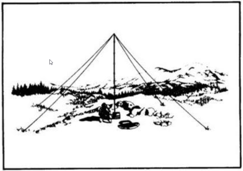
The AS-2259 consists of a pair of crossed dipoles on a common feedpoint. The dipoles are cut for roughly 6.2 and 9.3 MHz. The wires are installed in an inverted-vee configuration from the top of a 4.5m (15 foot) mast of about 5cm (2 inch) diameter, that also serves as the outside of a low-loss coax feedline. At the base, the mast screws directly into the antenna jack on the top of a portable HF radio with a built-in tuner. The ends of the wires are staked out very close to the ground, as shown here:

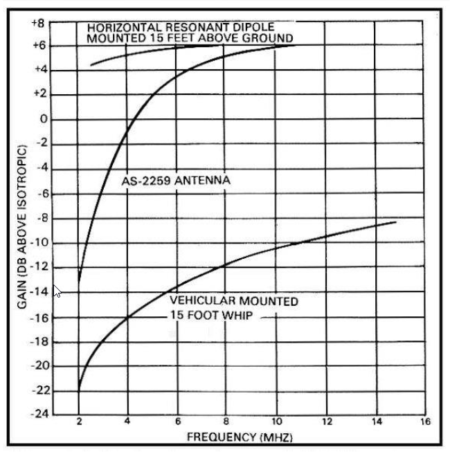
The AS-2259 works fairly well on 40m and 60m, but performance drops off below that. Here is the efficiency plot from the official documentation:

At 4 MHz (the top of the IARU Region 2 80m band) it is only down about 6 dB from a dipole – that doesn’t seem too bad. But that is based on having a radio with a wide-range tuner connected directly at the base of the mast. (It should be similar with a remote autotuner at that point.)
One problem with many ham attempts to copy the antenna is that they feed the antenna with 15m (50 feet) or more of standard coax cable, which can add 10 dB of loss due to SWR compared to the low loss, rigid coax feed built into the mast. And at the station end, the impedance is often low, and tuner losses on 80m can be 3 dB or more. The result is an antenna that may be only a few percent efficient.
For reference, the stock military antenna by itself would have a feedpoint impedance of around 13 – j530 ohms on 3.8 MHz and 825 + j350 ohms on 7.2 MHz. At the base of the mast (which doubles as a low-loss coax feedline) this would be something like 1 – j135 at 3.8 MHz and 15 – j100 on 7.2 MHz. That is the impedance that a tuner at the base of the mast would have to match, or if coax is plugged into the jack at the base of the mast. (Use the first numbers if you are making your own version with the coax connected at the feedpoint.)
We can use Owen Duffy’s online Transmission Line Loss Calculator, or AC6LA’s TLDetails program, to calculate the losses for different lengths and types of coax based on these numbers, as well as the resulting impedance that a tuner has to match. I strongly recommend that anyone using such an antenna perform this analysis for their specific cable type and length: it points out the need for keeping the cable short and using low-loss types, or using a remote autotuner at the antenna.
For example, DX Engineering has instructions on how to build a ham version, using 30m ( 100 feet ) of RG-8X coax. On 80m the loss in the coax is around 15 dB, or about 3% efficient. That’s in addition to the 6 dB loss compared to a standard dipole and any tuner losses. The coax losses are about 4 to 5 dB on 40m and 60m.
One of the comments that came out after the emergency communications for Hurricane Katrina was how poorly the AS-2259 (and especially ham clones of it) worked on 80m.
Improving the AS-2259
Fortunately it isn’t difficult to improve the AS-2259, especially if you are building your own copy.
- First, make the wires resonant on 40m and 80m. Or 60m if you will be using it. That reduces most of the losses due to the tuner and high SWR. If you don’t have room for full sized elements, use loading coils. (Using a dual band dipole for 40m / 160m, in conjunction with an 80m wire, can work well, without needing a tuner.)
- Raise the feedpoint when practical. Another 2 – 3m (5 – 10 feet) may be useful without being too difficult for a portable unit.
- Keep the ends of the wires higher off the ground to reduce ground losses. Use longer ropes on the ends to keep the ends of the wires out of reach of a tall person.
That results in an antenna that is just two (or 3) dipoles on a common feedpoint, as many hams are already using. But the difference in performance on 80m compared to the original AS-2259 can be significant, especially if you are feeding it through a long length of coax.
BACK TO:
antennas for different applications
RELATED LINKS:
general notes on portable antennas
EXTERNAL LINKS
US Army: AS-2259/GR technical manual
W4RNL: some basic 3-band NVIS antennas
Owen Duffy: RF Transmission Line Loss Calculator (runs online)
AC6LA’s TLDetails program (download and run under Windows)
(note: both of the following designs need a short, low-loss feedline to be reasonably efficient on 80m)