how to adjust a manual antenna tuner
last updated 28 February 2025.
Yes, this is a long article, because I include a lot of introductory material explaining the functions of the various controls and connectors, and how to connect it into the circuit. And there are many different tuners available. These are common sources of problems, especially for those who have not used a tuner before.
While automatic antenna tuners are quite common these days, manual tuners are still popular for a number of reasons: they often have a wider matching range, can be used with virtually any radio, most don’t require DC power (other than for dial lamps), and often can be built at home using parts from a hamfest.
Adjusting a manual antenna tuner can be bewildering to a beginner, but it really isn’t difficult once you get used to it. It does vary with different tuners, so let’s walk through the process.
learning about your tuner
Let’s start by looking at the controls and other bits on the antenna tuner itself. The basic tuner usually requires 2 or 3 controls, but there may be additional options. Here is a simple one:
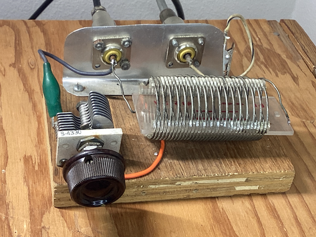
The two controls are the variable capacitor on the left, and the clip on the coil on the right. (Moving the clip on the coil varies the number of turns of the coil being used.)
Here is a fancier version: the circuit is the same, but in a nicer case, and with a rotary inductor instead of a clip on the coil.
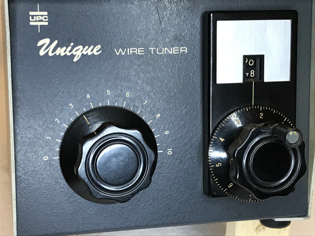
The mechanism on the right rotates the coil under a roller that makes contact: it does the same thing as the clip, but can be set to fractional turns. Because the coil is not visible to the operator, it has a counter to indicate how many turns of the coil are being used. Such a “roller inductor” allows a more accurate match, although they are slower to adjust for large changes.
Other tuners will use switched taps on an internal coil: again changing the number of turns being used, but in discrete steps.
Here is a more common design, with 3 controls:
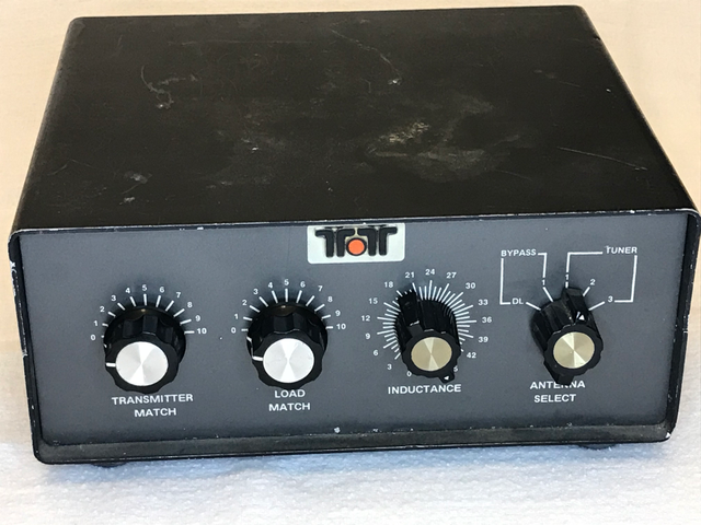
The coil (the knob marked “INDUCTANCE”) has 45 switch positions, far more than most such tuners, which often are limited to less than 24 by the availability of suitable switches.
The two knobs on the left marked “TRANSMITTER MATCH” and “LOAD MATCH” are variable capacitors. Together with the coil, they make up the 3 adjustments. The switch on the far right selects which of the 4 output connectors is being used. Note that one side is marked BYPASS, and the other TUNER. The “DL” (dummy load) position is never tuned (and, if it is just a connector to an external dummy load, can also be used for another antenna that doesn’t need the tuner). Antenna connector #1 can be used either directly without using the tuner (“BYPASS”), or through the tune (“TUNER”). Connectors #2 and #3 can only be used through the tuner.
These details will vary with the specific tuner, and not all tuners will include an antenna switch. But it is important to be able to understand how to use the controls: it isn’t uncommon to try to tune an antenna, only to find that the switch is set to the wrong connector, or the tuner is in bypass mode, where the controls have no effect.
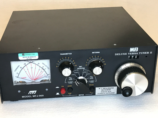
Here is a more fancy antenna tuner. Again, the three main controls are the coil (on the right side, with the turns counter), and the two variable capacitors at top center (labeled TRANSMITTER and ANTENNA). The switch below the capacitors selects which coax connector to use, and whether it runs directly or through the tuner. On the left is a power / SWR meter, used for adjusting the antenna tuner, and the row of buttons along the bottom center control the meter.
Notice that the switch includes two COAX connectors, a DUMMY LOAD, and something marked BAL LINE WIRE (each of which can be used in BYPASS or TUNER mode). We’ll explain the BAL LINE WIRE position in a moment.
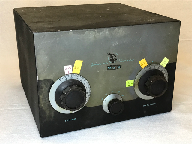
Some tuners, like this old “Johnson Viking Matchbox”, have a band switch instead of an adjustable coil. The coil setting is pre-determined for each band, and selected by the switch. The two big knobs then adjust variable capacitors.
Note the colored stickies on the panel: this is how I mark my tuners to save time when changing bands. I only have to adjust the tuner once, then I just return the knobs to the marks for the appropriate band. You can also record the settings using the dial scales, but I have found that the pieces of sticky notes are faster, and I can color-code them for each band.
With this particular tuner, there is a lot of interaction between the two controls: I adjust one, then the other, and back and forth many times. I discovered it is easier to use two hands and turn both knobs at the same time! Once you try it, you will get the feel of which way you need to turn each knob for the load you are trying to match, so the SWR reduces to a low value (then it may require a slight readjustment of each control).
So now you should have an idea of what the controls do. Let’s take a quick tour of the back of the tuner.
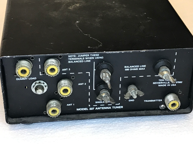
On the left we see the 4 output coax connectors: “DUMMY LOAD”, and ANT1 through ANT3. These go to the antenna selector switch. The TRANSMITTER connector on the right goes to the transmitter. Now, what about all that mess in the middle? This is BAL LINE WIRE: an option to use BALANCED LINE or an END-FED WIRE (which are connected to ANT3 on this tuner, unlike the prior example).
This is actually a common method of permitting an antenna tuner to work with a single end-fed wire, or with a balanced feedline. In this case, the dotted line includes the ANT3 connector, the SINGLE WIRE post at the bottom center, and the two BALANCED LINE binding posts in the top right area. Other tuners will often work in a similar way, but the connectors will be arranged differently.
Here is how to make sense of it:
The coax connector ANT3 is also connected internally to the SINGLE WIRE binding post. So if you want to use an end-fed wire, just connect it to the SINGLE WIRE post and choose ANT3 on the front panel switch. (The ground connection goes to the binding post marked GND.) When using an end-fed wire that comes all the way to the station, you generally do NOT need to use an unun – just run the wire directly to the tuner.
To use a balanced feedline, connect it to the two binding posts marked BALANCED LINE. Most importantly, also connect a short piece of wire between the SINGLE WIRE binding post and one of the BALANCED LINE binding posts, as shown by the line. Then choose ANT3 on the switch.
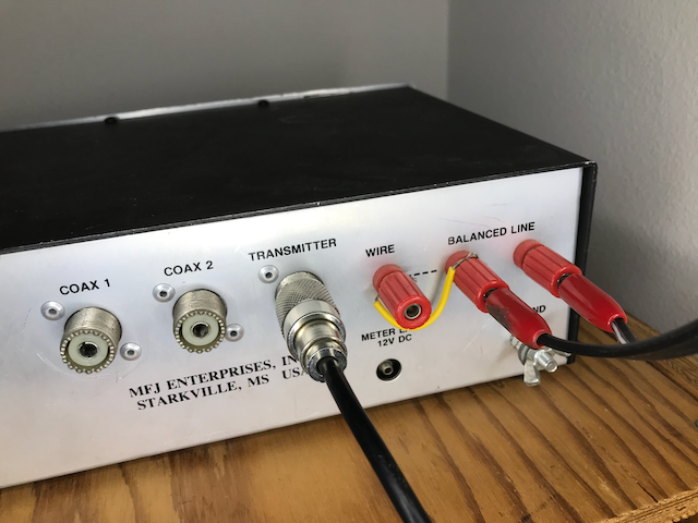
Here is a rear view of a different antenna tuner, showing twinlead connected to the BALANCED LINE terminals on the far right, using banana plugs. The yellow jumper wire connects one side of the balun to the SINGLE WIRE terminal.
Most manual antenna tuners that work with both coax and with a balanced output use an internal balun that is connected in this manner. If you forget the short piece of wire, then the antenna isn’t connected to the tuner, and it won’t work with the balanced line terminals.
What if you want to match a single wire antenna, but the tuner only has coax outputs? Put a banana plug on the end of the wire and stick it into the center of one of the coax connectors. Don’t forget the ground system.
This doesn’t cover every possible tuner, of course, but it should help you figure out how your tuner works, and how to connect it.
connecting the tuner
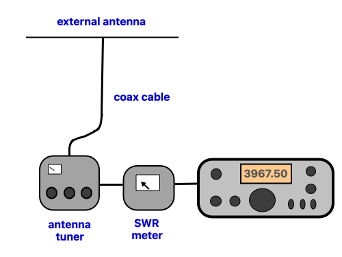
Now that you understand about the tuner controls and connectors, connect the tuner between the antenna and the radio (or the SWR meter, if you are using an external one). Generally, this involves plugging the cable from the antenna into the ANTENNA port on the tuner, and a short coax jumper cable from the TRANSMITTER port on the tuner to the antenna connector on the radio (or to the ANTENNA port on the SWR meter, then the TRANSMITTER port on the meter connects to the radio using another short piece of coax cable).
Some tuners will include an antenna switch, and several different antenna connectors. In that case, remember which antenna connector you used.
setting up the transmitter
In order to adjust your antenna tuner, you have to transmit a signal through it to get an indication of SWR. To reduce the stress on the tuner (and on the transmitter, which will see a high SWR during the tuning process), it is generally best to reduce the transmitter power during this stage. A power of 10% of the transmitter rating is generally low enough not to cause any problems. If you are using an external amplifier, turn it off, and just use the exciter (at low power) for tuning. Even though the antenna is not tuned, you are still transmitting a signal that can interfere with other stations. Generally the idea is to use as low a power as you can, while still getting a good indication of SWR.
You generally also want to use a steady carrier signal, because if the output power is varying it may make it difficult to determine whether your SWR is increasing or decreasing, especially with SSB. There are several ways to do this.
Perhaps the easiest way, if you have a CW key connected, is to turn down the transmitter power, key the radio in CW mode, and increase the power until you see an indication of SWR. For a 100 watt transmitter, this is often around 3 – 10 watts (depending on your SWR meter). Then you can lock the key down while tuning (don’t leave it on too long), and use the key to send your callsign for ID when you are finished. What control you use to reduce the output power will vary from one radio to the next.
If you don’t have a key connected, you can switch to AM mode and key the microphone without any audio input. That should generate a steady carrier at about 25% of rated PEP output. You can also use FM mode, but that will give 100% output power, so you will want to decrease it somehow.
You can use SSB by feeding an audio oscillator into the microphone circuit and adjusting the level until you get around 5 – 10 watts output (for a 100 watt transmitter), but just keying the mic in SSB mode by itself should NOT produce enough RF to operate most SWR meters.
adjusting the tuner
Make sure that the the antenna is connected to the tuner, and you have the antenna selector switch (if the tuner has one) in the proper position. Set
The received signal will also pass through the tuner, so a good first step is to adjust the tuner for maximum received signal either by ear, or on the S-meter, with the radio listening on the desired frequency. Background noise is usually adequate for this step.
If you only have two controls, set the/a capacitor to mid-scale, and try different coil settings until you get the most signal. Then adjust the capacitor for maximum. The controls likely will interact.
With 3 controls (a “T-network tuner”), set one capacitor to maximum, and use the other two as if it only had 2 controls. If that doesn’t seem to work, set the other capacitor to maximum instead and try again.
Note that tuners are not consistent with which end of the scale corresponds to maximum capacitance. I take the cover off and look inside to find the knob setting where the two sets of capacitor plates are fully meshed together – that is maximum capacitance. Then I loosen the set screw that holds the knob on and reposition the knob so it points to the biggest numbers on the logging scale, as that is what I associate with maximum capacitance, and I often want to set the capacitor to that point.
The two controls will interact a bit, but this should give you a reasonable starting point for further adjustment. If you couldn’t hear any difference in received signal, double check that you are switched to the correct coax connector, that the tuner is not in BYPASS mode, and the antenna is connected to the other end of the coax.
Make sure you are on an empty frequency, so you don’t cause QRM, and key the transmitter so it puts out an unmodulated carrier (just keying the mic in SSB mode is not sufficient, as described previously), and adjust the power so you can see reasonable forward power on your SWR meter. Then, while watching the SWR meter, adjust the controls alternately for minimum SWR, as described previously for maximizing received signal strength. If you have to adjust a switched coil, STOP TRANSMITTING while you do so. (“Hot switching” the coil is a common way to damage the switches in tuners.) With a roller inductor, you can crank it through its range while transmitting. You often will need to make adjustments to both controls. If you can’t get the SWR low enough, and you are using a tuner with 3 controls, then you can see if reducing the capacitor that was initially set to maximum will help. (The tune will be most efficient with one capacitor set to maximum and as little inductance as needed, but it isn’t always possible to get a good match at this setting.) With a switched coil, you may have to try different settings to get a good match.
Be cautious about leaving the transmitter keyed for too long during this process, especially if you can’t reduce the power. The transmitter is operating into a high SWR until the tuner is tuned.
If you have an antenna analyzer that reads SWR, you can use that instead of a transmitter and SWR bridge. Then you don’t need to transmit to make the adjustments.
In some cases, the tuner adjustments will be very sensitive to the exact setting of the capacitors, requiring you to tune slowly to find the optimum setting. Having large knobs on the capacitors, or reduction drives so it takes more turns to go from minimum to maximum, will make it easier.
If you have trouble, attach a dummy load to the tuner in place of the antenna and practice tuning into that.
How low of an SWR do you need? While it is feels good to get the SWR as low as absolutely possible, there isn’t much operational benefit in getting it below about 1.5 : 1, unless your radio is very finicky.
back to:
beginners’ guide to antenna tuners
standing wave ratio (SWR) – main article
antenna tuner efficiency and ratings