simple doublet antenna
last updated 23 December 2024.
A “Doublet” is simply a center fed wire, usually horizontal or in an inverted vee configuration, fed with parallel-conductor line. This forms an effective multiband antenna, because the feedline losses can be relatively low, even at high SWR, as will occur on some bands. It is generally used with an antenna tuner in the shack, although some versions can give a low SWR on a limited number of bands with careful choice of the wire and feedline lengths. This is a very simple and inexpensive antenna that has been popular for multiband use for generations of hams.
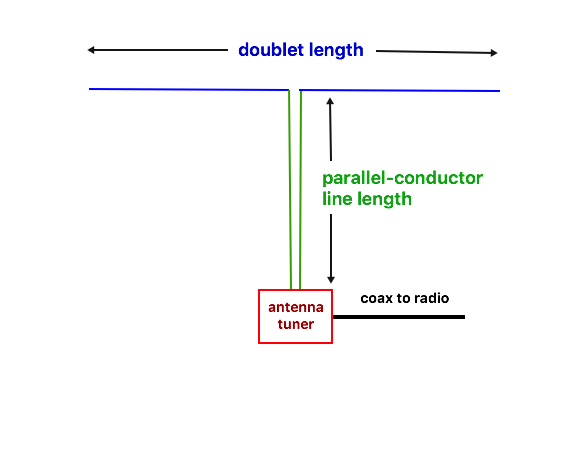
While the concept is simple, as is the antenna itself, there are some important considerations for good performance.
The efficiency is reduced as the doublet length is made less than about 1/2 wavelength. Generally, it is still reasonable with a length of 1/3 wavelength, but the losses in the feedline and tuner can increase quickly when the length is 1/4 wavelength or less. Sometimes that is an acceptable trade-off for multiband use when a longer antenna isn’t practical. Efficiency usually determines the lowest usable frequency for a particular antenna length. Often, the doublet is made 1/2 wavelength on the lowest frequency – basically a half-wave dipole – but this isn’t a requirement.
The radiation pattern depends on the doublet length in wavelengths, so will vary from one band to the next as the frequency changes. At higher frequencies, where the wire may be several wavelengths long, the pattern divides into multiple lobes and nulls. The antenna will still work, but may be noticeably stronger (or weaker) in some directions.
sample radiation patterns
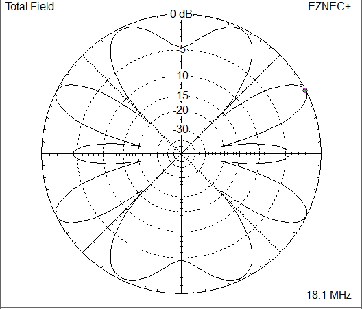
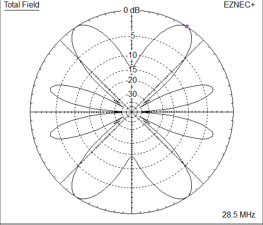
To give a sense of what the radiation patterns look like, here are sample plots of a doublet with a length of 40m ( 131 feet) installed at a height of 10m ( 33 feet ), when operated on different bands. In each case, the antenna is aligned with the vertical axis of the plot.
On 80m where the antenna is 1/2 wavelength, the antenna is exactly the same as a half wave dipole. The pattern doesn’t show the traditional nulls off the end due to ground reflections.

On 40m, where the antenna is 1 wavelength, the pattern is still maximum broadside to the antenna, but with a little bit more gain, and the lobes are a little narrower.
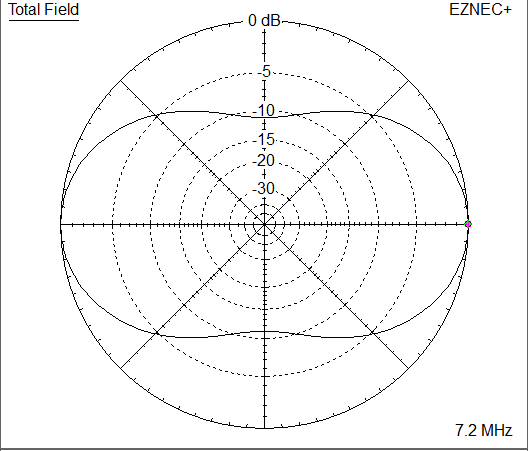
On 30m the antenna is just short of 1.5 wavelengths, and the lobes off the ends of the wire are becoming more pronounced.
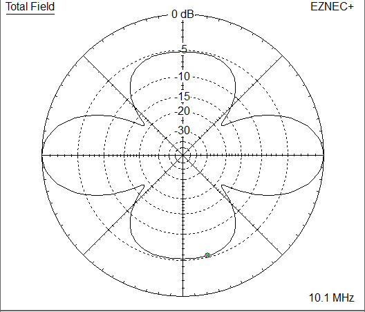
On 20m the antenna is 2 wavelengths long. There is are nulls broadside to the antenna, and the maximum lobes are about 45 degrees from the wire ends.
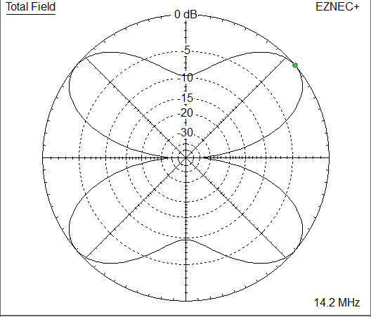
On 17m, where the wire is a little over 2.5 wavelengths, the pattern is much more complex.
Up at 10m the wire is 4 wavelengths long, the lobes are stronger, but narrower.
Intermediate bands will have other patterns with various numbers of lobes and nulls.
So a doublet can provide radiation in many different directions, but not necessarily in the same directions on each band. They can make lots of contacts, but if you are interested in a particular target location on a specific band, you may need to adjust the antenna orientation to accommodate it.
feeding a doublet
Let’s start by looking at some typical feedpoint impedances for a doublet. In this case, we will use the 40m long ( 131 feet) doublet, which is 1/2 wavelength on the 80m band, installed at a height of 10m ( 33 feet ), and record the impedance on each HF ham band plus 160m. You can scale these to other antenna lengths, and estimate the impedance of intermediate values. I’ve also provided the expected SWR relative to both 50 ohm coax and 400 ohms (a common value for nominal “450 ohm” windowed twinlead).
| band | freq | impedance | SWR (50) | SWR (400) |
|---|---|---|---|---|
| 160m | 1.9 MHz | 8 – j1000 Ω | 2500 | 160 |
| 80m | 3.6 MHz | 51 – j0 Ω | 1 | 8 |
| 60m | 5.35 MHz | 400 + j1000 Ω | 75 | 10 |
| 40m | 7.1 MHz | 3600 – j2500 Ω | 105 | 14 |
| 30m | 10.125 MHz | 100 – j400 Ω | 36 | 8 |
| 20m | 14.2 MHz | 3200 + j0 Ω | 65 | 8 |
| 17m | 18.1 MHz | 100 – j200 Ω | 11 | 5 |
| 15m | 21.3 MHz | 2700 + j600 Ω | 57 | 7 |
| 12m | 24.9 MHz | 115 – j430 Ω | 35 | 8 |
| 10m | 28.5 MHz | 2100 + j650 Ω | 45 | 6 |
We can use these values later to calculate the actual impedances and losses for a given feed system.
While a doublet is typically fed with balanced line to a wide-range tuner, there can still be problems feeding it on some bands. Let’s look at a typical SWR curve (relative to 50 ohms) to see why. This is for our 40m long doublet fed with 20m (65 feet) of 400 ohm windowed twinlead:
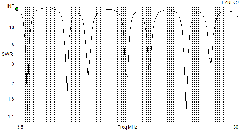
There are several frequencies where the SWR is low enough that we don’t need a tuner. However, they don’t fall in the ham bands. The low SWR readings are around 4.75, 9.5, 12, 16.25, 19.25, 23.7, and 26.75 MHz.
And there are ranges where the SWR relative to 50 ohms is very high. Here are the nominal SWR values for some HF ham bands:
| band | SWR |
| 80m | 50 : 1 |
| 40m | 110 : 1 |
| 30m | 20 : 1 |
| 20m | 65 : 1 |
| 17m | 36 : 1 |
| 15m | 57 : 1 |
| 12m | 30 : 1 |
| 10m | 35 : 1 |
The resistive component of impedance at the end of the parallel conductor line ranges roughly from 25 to 5000 ohms: that will cause problems for many tuners, particularly on 40m (in general, the frequency at which the antenna is a full wavelength long).
The specific impedance that the tuner needs to match depends on the length of the doublet, and the length and type of the feedline. We can move the curve around by changing these lengths. Here’s what happens when we use 25m ( 82 feet ) of feedline instead:
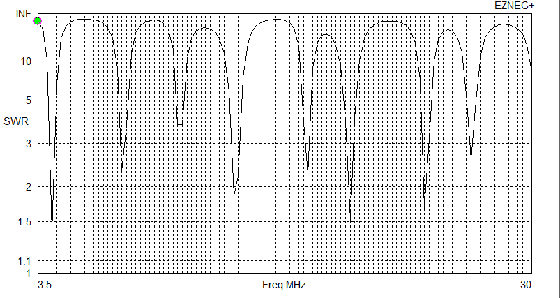
We still see a similar pattern of peaks and dips, but the frequencies have changed. Now the SWR in the ham bands looks like this:
| BAND | SWR |
| 80m | 32 : 1 |
| 40m | 36 : 1 |
| 30m | 65 : 1 |
| 20m | 1.3 : 1 |
| 17m | 3 : 1 |
| 15m | 31 : 1 |
| 12m | 17 : 1 |
| 10m | 47 : 1 |
The SWR on all the bands except 30m and 10m has improved, and 20m may not even need a tuner (although a balun is still a good idea). And, even though the SWR is lower on many bands, the tuner must still be able to match over a 20 : 1 SWR to cover all bands.
Similar effects can be achieved by changing the doublet length instead of the feedline length, although I don’t have space here to give a more examples. The practical effect, however, is that, when installing a doublet with whatever length of feedline will conveniently reach to the shack, you may find that it your tuner won’t tune it on some bands. In that case, experiment with changing the feedline length (adding more feedline may be easier than shortening it if it was already cut to a minimum length) to find a combination that your tuner will match satisfactorily. Often, it may be easier to match a doublet that is not a resonant length on the lower bands.
One reason for providing the original table of feedpoint impedances was to help calculate the actual impedance that the tuner needs to match on each band for different feedline types and lengths. By feeding those values (and frequencies) into a suitable calculator (such as TLLC, which runs in a browser window, or TLDetails, which runs on a Windows PC), and setting the type and length of feedline, you can see the actual line loss and the impedance at the tuner end of the line.
is there an ideal combination?
One might then ask whether it is possible to come up with a combination of doublet and feedline lengths that would make it easier to match on several ham bands. The answer is “yes”: the G5RV and ZS6BKW are perhaps the best known examples. But until I get that article written, you will have to refer to the external links listed below for more information, including the general approach by AA1LL.
the effect of coax between the balun and the tuner
A popular approach is to terminate the balanced line outside the house at a balun, then run coax from there into the station, with an unbalanced tuner in the shack. While this often works well enough, with an unfortunate combination of dimensions it can result in high losses in the coax. For example, in the original 40m case and using a 1 : 1 current balun, the loss in 6m ( 20 feet ) of RG-213 coax would be about 3 dB, or half your power dissipated in the coax, even though the matched line loss at that frequency is insignificant (less than 0.1 dB). There is a further issue that the combination of the two feedlines may create an even wider potential range of impedances that the tuner has to match, including lower impedances, which tend to be less efficient for many tuner types. I’ve seen this effect on 20m with less than 50cm ( 20 inches ) of coax between the balun and the tuner. For that reason I try to keep the coax as short as possible between an unbalanced tuner and an external balun.
To calculate this for your own feed system, use the method described above to calculate the impedance at the end of the ladder line, record those (along with the line losses), then repeat the process using those impedances along with the length and type of the coax between there and the tuner in the shack. This doesn’t include the losses in the tuner, which can be important, especially for low resistance values, but it will give you and idea of the actual losses (adding the losses for both types of feedline), and may help to catch some extreme cases.
back to:
Field Day antenna selection guide
related links
simple construction of wire antennas
analysis of current distribution along a wire
the importance – or not – of antenna resonance
antenna tuner efficiency and ratings
Ten-Tec AC5 balanced antenna tuner
external links
FEEDLINE CALCULATORS
Owen Duffy: Transmission Line Loss Calculator (TLLC) (runs in a browser window)
AC6LA: TLDetails program (runs on a Windows PC)
REFERENCE ARTICLES:
W4RNL: Frequently Asked Questions about the All-Band Doublet
W4RNL: The G5RV Antenna System Revisited
DJ0IP: Open-Wire-Fed Antennas
Owen Duffy: Optimizing a typical G5RV
Owen Duffy: Minimum length of a non-resonant multi-band dipole
Owen Duffy: Is the 133 foot centre fed multiband dipole a no-brainer
Owen Duffy: G5RV according to G5RV
AA1LL: Low-Reactance Multi-Band Center-Fed Wires
G3TXQ (via KD6RF): G5RV Antenna (and ZS6BKW)
W4RNL: Backup Antenna for 80-20m
W4RNL: A 102 Foot Center-Fed Multi-Band All-Band Dipole Data Compedium
W4RNL: A 135 Foot Center-Fed Multi-Band All-Band Dipole Data Compedium
W4RNL: A Vertical Doublet for 30-10 Meters
W4RNL: The 44 Foot as a 40-10 Meter
W4RNL: The Zig-Zag Dipole-Doublet
Owen Duffy: Feeding a G5RV
Owen Duffy: Bowral G5RV for local contacts